Knock control device for internal combustion engine

A control device and engine technology, applied in the direction of engine control, automatic control, automatic control, etc., can solve the problems of operability deterioration and fuel performance deterioration, and achieve the effect of preventing operability deterioration, preventing excessive lag, and realizing the effect of ignition period.

Inactive Publication Date: 2013-04-03
SUZUKI MOTOR CORP
View PDF6 Cites 5 Cited by
  • Summary
  • Abstract
  • Description
  • Claims
  • Application Information

AI Technical Summary

Problems solved by technology

[0005] At this time, if the control of the ignition timing is unstable and vibrates greatly, the deterioration of drivability due to torque fluctuations, the deterioration of output due to excessive hysteresis, and the deterioration of fuel performance become problems.

Method used


Image

  • Knock control device for internal combustion engine
  • Knock control device for internal combustion engine
  • Knock control device for internal combustion engine

Examples


Embodiment Construction

[0026] Next, embodiments of the present invention will be described in detail.

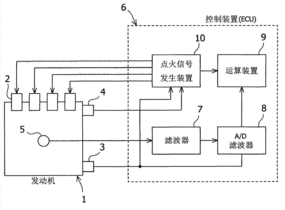
[0027] figure 1 It is a system configuration diagram showing an engine knock control device according to an embodiment of the present invention.

[0028] The engine 1 is a spark ignition type internal combustion engine, and an ignition coil 2 is provided for each cylinder's ignition plug (not shown). In addition, the engine 1 is provided with a crank angle sensor 3 , a cam angle sensor 4 , and a knock sensor 5 .

[0029] The crank angle sensor 3 is synchronized with the rotation of the crankshaft of the engine 1, and outputs a unit angle signal for a unit crank angle.

[0030] The cam angle sensor 4 is synchronized with the rotation of the camshaft of the engine 1. In the case of 4 cylinders, it outputs a reference angle signal corresponding to the reference crank angle position of each cylinder at every 180° of the crank angle. A reference angle signal corresponding to the reference crank angl...


PUM


Abstract

Ignition-period stability in normal state and transition state is realized. Whether knock exists is detected based on a signal from a konck sensor (S6). The ignition period is delayed when the knock exists (S7). The ignition period is brought forward when no knock exists (S12). After knock is detected and the ignition period is delayed, knock control sensitivity is reduced in a preset response delay time period (S4,S5) for preventing over-delay. Besides, when no knock exists and the ignition period is brought forward, bringing-forward of the ignition period is forbidden in a preset response delay time period (S11). According to a preset studying condition, after the knock is detected and the ignition period is delayed, the ignition period is temporarily kept to the delayed ignition period, and the changed response delay time of the knock level relative to the ignition period is studied (S3,S14-S17).

Description

technical field [0001] The present invention relates to a knock control device for an engine that detects the presence or absence of knock (knock) based on a signal from a knock sensor, and performs knock control that retards or advances ignition timing accordingly. Background technique [0002] In general knocking control, a knocking sensor that outputs a signal of a vibration waveform corresponding to the knocking state of the engine is used to detect the presence or absence of knocking based on the signal from the knocking sensor, and when there is knocking, the ignition timing is delayed. The ignition period is advanced. [0003] In more detail, control is performed as follows. Vibration is detected by a knock sensor installed on the surface of the cylinder. The vibration waveform is subjected to band-pass filter processing for extracting only the frequency specific to knocking and window processing for extracting only the vibration waveform in the knocking occurrence ...

Claims


Application Information

Patent Timeline
Patent Type & Authority Applications(China)
IPC IPC(8): F02P5/15
CPCF02D2041/1431F02P5/152F02D35/027F02P5/1523Y02T10/46Y02T10/40
Inventor 北隅仁小笠原茂
Owner SUZUKI MOTOR CORP
Why Eureka
Try Eureka