Resonance-type magnetoelectric sensor for ferromagnetic material defect detection and detection method thereof

A magnetoelectric sensor and defect detection technology, applied in the direction of material magnetic variables, etc., can solve the problems of small magnetic field range, large volume, unsuitable for leakage magnetic field detection, etc., to achieve a wide magnetic field detection range and improve the effect of magnetic sensitivity

Inactive Publication Date: 2013-04-03
JIANGSU UNIV
View PDF6 Cites 11 Cited by
  • Summary
  • Abstract
  • Description
  • Claims
  • Application Information

AI Technical Summary

Problems solved by technology

Among them, the magnetic flux leakage detection method is widely used because of the simple signal processing circuit and simple display equipment. It is especially suitable for the detection of cracks in steel pipes and broken wires of steel wire ropes. Its core part is a sensor for detecting magnetic flux leakage caused by material defects. The Hall sensor based on the Hall effect is widely used in magnetic detection. As we all know, the Hall sensor is suitable for the detection of medium-strength magnetic fields, but it is difficult to detect weak leakage magnetic fields, so it is difficult to detect small defects.
Fluxgate sensors, SQUID, etc. are more sensitive than Hall sensors, but fluxgate sensors have not been used in the fie

Method used


Image

  • Resonance-type magnetoelectric sensor for ferromagnetic material defect detection and detection method thereof
  • Resonance-type magnetoelectric sensor for ferromagnetic material defect detection and detection method thereof
  • Resonance-type magnetoelectric sensor for ferromagnetic material defect detection and detection method thereof

Examples


Example Embodiment

[0025] Example

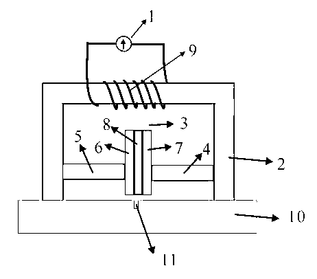
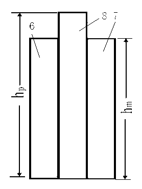
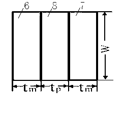
[0026] Such as Figure 1-5 As shown, a magnetoelectric element with a length of 12.5 mm, a width of 16 mm, and a thickness of 3 mm was fabricated. The length hm=12mm, width w=6mm, thickness tm=2mm of each magnetostrictive material block 6 and 7 of Terfenol-D material used in the magnetoelectric element; the length hp= of the piezoelectric material block 8 of PZT5A material used 12.5mm, its width and thickness are the same as those of magnetostrictive materials 6,7. A permanent magnet 3 of NdFeB material with a diameter of R=6mm and a height of wm=4mm is placed at one end of the magnetoelectric element to realize the bias magnetization of the magnetostrictive material blocks 6,7, and the bias magnetic field is along the length of the magnetoelectric element direction. The magnetoelectric element is the polarized Pb(Zr 1-x Ti x )O 3 (PZT5A) material and Terfenol-D (TbDyFe) material are pasted with epoxy resin. The supporting beams 4 and 5 are made of organic gl...


PUM


Abstract

The invention discloses a resonance-type magnetoelectric sensor for ferromagnetic material defect detection and a detection method thereof. According to the sensor, a magnetizing coil connected with a frequency-stabilization amplitude-stabilization excitation current source is wound at the middle position of the bottom section of a U-shaped soft magnetic piece; a magnetoelectric element and a permanent magnet are arranged between a left side section and a right side section; the magnetoelectric element consists of two identical magnetostrictive material blocks and a piezoelectric material block; the two magnetostrictive material blocks are respectively and fixedly adhered to the left and right side faces of the piezoelectric material block; the permanent magnet which is fixedly connected with the magnetoelectric element is arranged between the bottom end of the magnetoelectric element and the gap at the bottom section of the U-shaped soft magnetic piece, so that the frequency of an alternating current exciting signal is the same as the resonance frequency of the magnetoelectric element; and moreover, the tops of the left and right side sections of the U-shaped soft magnetic piece are tightly combined with the tested piece and move along the surface of the tested piece, the voltage of a silver electrode layer on the piezoelectric material block is monitored, and if voltage pulse exists, a defect exists at the position where the tested piece is opposite to the magnetoelectric element. An extremely weak magnetic field can be detected, and a magnetic field with moderate intensity can be detected.

Description

Technical field [0001] The invention relates to the field of nondestructive detection of magnetoelectric sensors, in particular to a magnetoelectric sensor used for nondestructive detection of defects in ferromagnetic materials. Background technique [0002] In the process of manufacturing and using ferromagnetic materials such as oil pipelines, steel wire ropes, steel plates, etc., due to friction, wear, corrosion and other reasons, various defects such as cracks, holes, and broken wires will occur. If the defects cannot be detected in time, it may be Will cause major accidents. [0003] At present, non-destructive testing methods for defects in ferromagnetic materials include magnetic flux leakage testing, magnetic particle testing, sonic testing, and radiographic testing. Among them, the magnetic flux leakage detection method is widely used because of its simple signal processing circuit and simple display equipment. It is particularly suitable for the detection of steel pipe c...

Claims


Application Information

Patent Timeline
IPC IPC(8): G01N27/83
Inventor 鲍丙好
Owner JIANGSU UNIV
Why Eureka
Try Eureka