
Highly-stable single-mode microwave optoelectronic oscillator

An optoelectronic oscillator and single-mode microwave technology, applied in microwave technology and optoelectronic fields, can solve the problems of increasing the oscillator side-to-move interval, bulky OEO system, and complex loop structure, achieving low cost, simple structure, The effect of suppressing side-touch noise

Inactive Publication Date: 2013-04-03
GUIZHOU UNIV
View PDF3 Cites 29 Cited by
  • Summary
  • Abstract
  • Description
  • Claims
  • Application Information

AI Technical Summary

Problems solved by technology

The multi-loop structure is complex and requires the use of long optical fibers, which makes the entire OEO system bulky. When using phase-locked loop technology to lock the starting frequency, it is theoretically necessary to adopt phase-locked control for each loop, which greatly increases the Cost and System Complexity
In addition, the multi-loop structure can only increase the side touch interval of the oscillator to a certain extent. Only when the number of loops is large can the single-mode start-up of OEO be effectively guaranteed;

Method used


Image

  • Highly-stable single-mode microwave optoelectronic oscillator
  • Highly-stable single-mode microwave optoelectronic oscillator
  • Highly-stable single-mode microwave optoelectronic oscillator

Examples


Embodiment 1

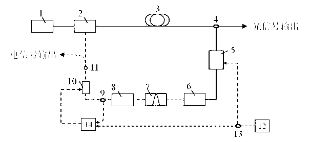
[0024] refer to figure 1 and 2 , a high-stable single-mode microwave photoelectric oscillator, including a laser 1, a modulator B5, a high-stable microwave source 12, and a phase-locked control module 14, wherein: the phase-locked control module includes a frequency divider 14a, a frequency mixer 14b, a low-pass filter Device 14c and algorithm controller 14d, frequency divider 14a is connected with mixer 14b, mixer 14b is connected with low-pass filter 14c, low-pass filter 14c is connected with algorithm controller 14d; The output end of laser 1 is connected to The input end of the modulator A2 and the output end of the modulator A2 are connected with a length of optical fiber 3, the output of a length of optical fiber 3 enters the optical coupler 4, one output of the optical coupler 4 is output as an optical signal, and the other enters the modulator The input end of B5, the output end of modulator B5 is connected with the optical input end of photodetector 6, and the elect...

Embodiment 2

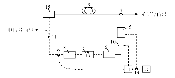
[0028] refer to figure 2 and 3 , a highly stable single-mode microwave photoelectric oscillator, comprising a direct modulation laser 15, a modulator B5, a highly stable microwave source 12, and a phase-locked control module 14, characterized in that: the output end of the direct modulation laser 15 is connected to a section of long optical fiber 3 , the output of a section of long optical fiber 3 enters the optical coupler 4, one output of the optical coupler 4 is output as an optical signal, and the other enters the input end of the modulator B5, and the output end of the modulator B5 is in phase with the input end of the phase shifter 10 connected, the output end of the phase shifter 10 is connected with the optical input end of the photodetector 6, the electric output end of the photodetector 6 is connected with the electric bandpass filter 7, and the output of the electric bandpass filter 7 enters the microwave amplifier 8. The output of the microwave amplifier 8 is con...


PUM


Abstract

The invention discloses a highly-stable single-mode microwave optoelectronic oscillator. A modulator B (5) is arranged in an optoelectronic oscillator (OEO) loop and driven by a highly-stable microwave source (12), output modes of the oscillator can be chosen through a modulation mode locking process, and edge mode noise is inhibited through gain competition between the modes. Simultaneously a phase-locked loop theory is used for comparing output signals of the OEO with output signals of the highly-stable microwave source (12), a phase (or cavity length of the OEC) for controlling the output signals of the OEO is fed back, and finally stable single-mode OEO output is obtained. The highly-stable single-mode microwave optoelectronic oscillator can achieve frequency stabilization phase lock and single-mode operation of the OEO simultaneously, is simple in structure and low in cost, and has practical value.

Description

technical field [0001] The invention relates to the fields of microwave technology and optoelectronic technology, in particular to a photoelectric oscillator. [0002] Background technique [0003] An optoelectronic oscillator (OEO: Optoelectronic Oscillator) is an optical and electrical microwave / millimeter wave signal generating device. Its basic structure is to use a feedback loop composed of a light source, an electro-optic modulator, a photodetector, and an electric filter, and use the energy storage capacity of a long optical fiber to generate high-quality optical and electrical microwave signals. At present, the OEO system has some disadvantages due to its structural characteristics, which are mainly manifested in: the long optical fiber can store more light field energy in the loop and improve the quality of the generated signal, but this also brings about a large system size. , vulnerable to the external environment, making the output frequency unstable shortcomin...

Claims


Application Information

Patent Timeline
IPC IPC(8): H01S1/02
Inventor 江阳
Owner GUIZHOU UNIV
Learn More