Constant time control method, control circuit and switching regulator using same

A constant time, control method technology, applied in the direction of control/regulation system, regulation of electrical variables, instruments, etc., can solve problems such as slow transient response, complex compensation design, etc., to reduce the difference, good compensation, and reduce fluctuations Effect

Active Publication Date: 2013-04-03
SILERGY SEMICON TECH (HANGZHOU) CO LTD
View PDF3 Cites 51 Cited by
  • Summary
  • Abstract
  • Description
  • Claims
  • Application Information

AI Technical Summary

Problems solved by technology

[0012] In view of this, the purpose of the present invention is to provide a novel constant time control method and its constant time control circuit, so as to solve the problems of slow transient response and complicated compensation design in the prior art

Method used


Image

  • Constant time control method, control circuit and switching regulator using same
  • Constant time control method, control circuit and switching regulator using same
  • Constant time control method, control circuit and switching regulator using same

Examples


Embodiment 1

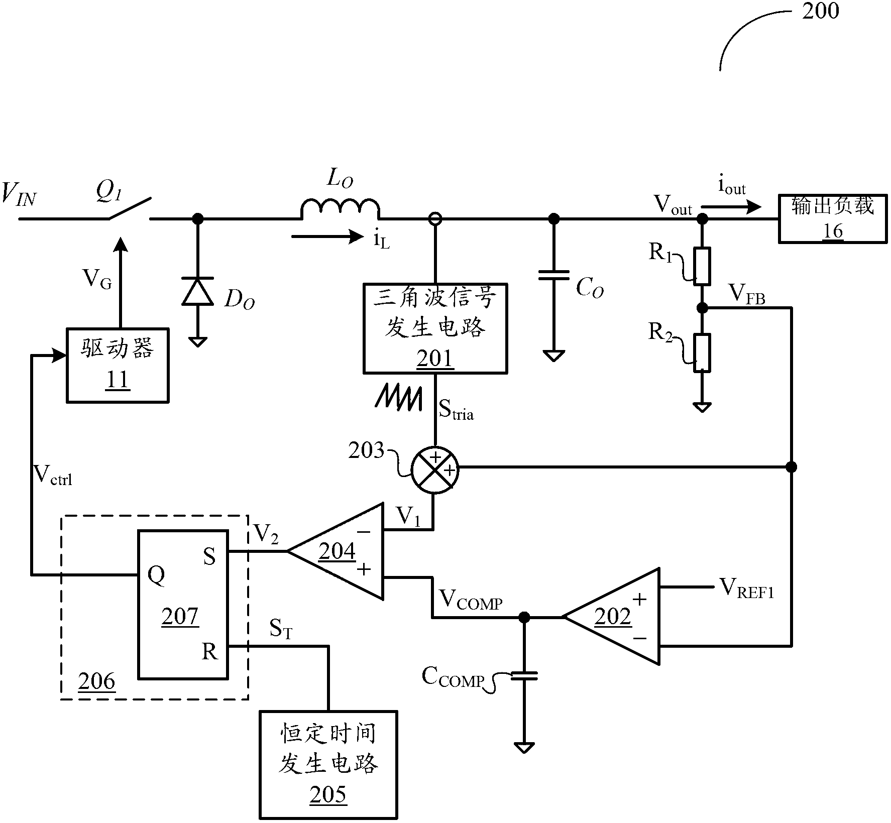
[0093] Referring to FIG. 2A, there is shown a schematic block diagram of a constant-time control circuit that can be used to control a switching regulator according to a first embodiment of the present invention.

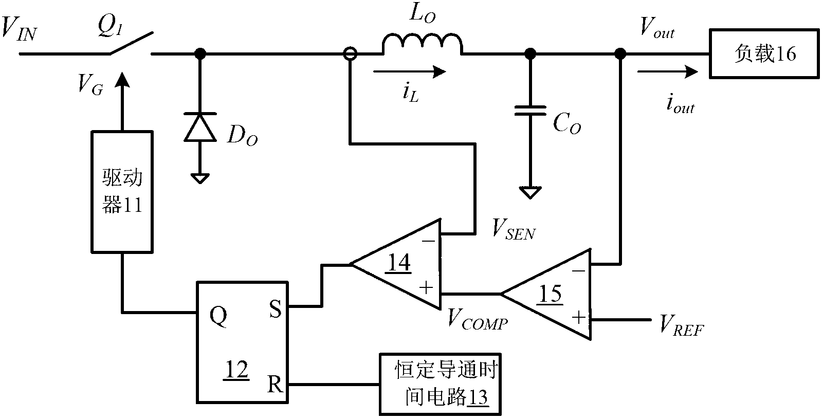
[0094] For the convenience of description, in this embodiment, the working principle of the constant-time control circuit 200 is described by taking a step-down switching regulator as an example. Here, the main power switching device Q 1 , Diode D 0 , inductance L 0 and output capacitor C 0 A power stage circuit that forms a step-down topology, and its input terminal receives the input voltage V IN , the output terminal is connected to a load 16 .

[0095] connected in series at the output voltage V out The voltage dividing resistor network composed of resistor R1 and resistor R2 between the equipotential is used as a voltage feedback circuit to receive the output voltage V at the output terminal out , so that a voltage feedback signal V representing the outpu...

Embodiment 2

[0118] exist Figure 2A In the embodiment of the constant time control circuit shown, when the output current jumps from low to high, due to the limitation of the minimum off-time mini_off, the inductor current cannot continue to increase, which affects the transient state of the system to a certain extent Responsive performance. If the minimum off time can be shielded during the transient response, the transient response can be further accelerated. The following will combine Figure 4 The shown specific embodiment of the constant time control circuit according to the second embodiment of the present invention specifies its specific implementation.

[0119] exist Figure 2A On the basis of the illustrated embodiment, the constant time control circuit 400 adds a shielding circuit 404 to shield the minimum off time during the transient response, further reducing the transient response time and improving the transient response performance.

[0120] Specifically, the shielding...

Embodiment 3

[0122] refer to Figure 5 , is a schematic block diagram of a constant-time control circuit according to a third embodiment of the present invention. In this embodiment, when the output current jumps, the constant time control circuit 500 directly prolongs the conduction time of the power switching device to complete the transient response as quickly as possible.

[0123] Specifically, in Figure 2A On the basis of the illustrated embodiment, the constant time control circuit 500 is added with a time extension circuit 505 . Specifically, the time extension circuit 505 includes a transient judging circuit 501 , an inverter 502 , an AND gate 503 and an OR gate 504 .

[0124] Transient judgment circuit 501 according to the voltage feedback signal V FB and the first reference voltage V REF1 The size relationship of the judgment of the occurrence of transient changes. It can be realized by different implementation methods, such as comparator and so on. When the output current...


PUM


Abstract

The invention relates to a constant time control method, a control circuit and a switching regulator using the same. The constant time control method includes: detecting output voltage of the switching regulator to obtain voltage feedback signals for representing the output voltage; detecting flow inductance current to obtain triangular wave signals for representing the inductance current; overlaying the triangular wave signals and the voltage feedback signals to generate a first control signal; calculating errors between the voltage feedback signals and first standard voltage, and compensating the errors to obtain a compensating signal; enabling the compensating signal to keep roughly constant; comparing the first control signal with the compensating signal to generate a second control signal; and controlling opening and closing of a power switching element in the switching regulator according to the second control signal and a constant time control signal so as to keep roughly constant of electric signals output by the switching regulator.

Description

technical field [0001] The invention relates to a power supply technology, more specifically, to a constant time control method and constant time control circuit applied to a switching regulator. Background technique [0002] The switching power supply is composed of two parts, the power stage circuit and the control circuit. The function of the control circuit is to adjust the turn-on and turn-off time of the switching system in the power stage circuit when the input voltage, internal parameters and external load change, so as to keep the output voltage or output current of the switching power supply constant. Therefore, in the design of the switching power supply, the selection and design of the control method are very important for the performance of the switching power supply. Using different detection signals and different control circuits will have different control effects. [0003] The control mode of switching power supply can be divided into fixed frequency contr...

Claims


Application Information

Patent Timeline
Patent Type & Authority Applications(China)
IPC IPC(8): H02M3/156
CPCH02M3/156H02M3/1566
Inventor 陈伟
Owner SILERGY SEMICON TECH (HANGZHOU) CO LTD
Why Eureka
Try Eureka