Automatic small-dip-angle dusty pipeline cleaning device

An automatic cleaning and dust accumulation technology, applied in the direction of removing smoke and dust, cleaning hollow objects, cleaning methods and utensils, etc., can solve the problems affecting the normal operation of the equipment, the difficulty of cleaning, and the high labor intensity, so as to improve product quality and output, avoid Secondary dust, the effect of ensuring normal operation

Inactive Publication Date: 2013-04-17
DENGFENG SONGJI CEMENT
View PDF7 Cites 27 Cited by
  • Summary
  • Abstract
  • Description
  • Claims
  • Application Information

AI Technical Summary

Problems solved by technology

In this way, it will inevitably lead to a reduction in the ventilation area of ​​the pipeline, and the original design of the dust-laden air flow will not be realized, which will directly affect the dust collection effect of the dust collector, and even affect the normal operation of the equipment system and product recovery.
[0003] In the prior art, when the diameter of the air intake pipe and dust-containing air duct of the dust collector is large enough to accommodate workers to perform operations, manual cleaning is generally used to deal with the formation of the dust layer; when the air intake pipe of the dust collector and the air duct containing dust When the diameter of the dust duct is small, the only way to remove the dust layer is to remove the duct
Even if the method of manual cleaning is used to deal with the ash layer, there are still technical defects such as difficult cleaning, high labor intensity, harsh working environment, and direct impact on the normal operation of the equipment.

Method used


Image

  • Automatic small-dip-angle dusty pipeline cleaning device

Examples


Embodiment Construction

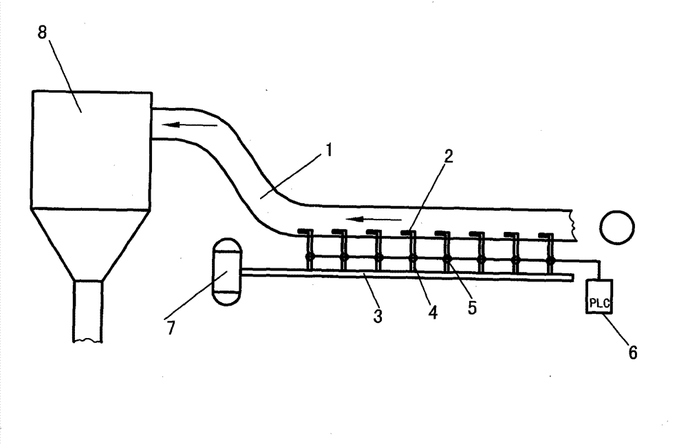
[0012] Below in conjunction with accompanying drawing and embodiment, the present invention is described in detail;

[0013] As shown in the accompanying drawings, the automatic cleaning device for the small-inclination dust pipeline is composed of a high-pressure main pipeline 3, several blowing nozzles 2, a corresponding number of solenoid valves 5 and branch pipes 4, an air pressure source 7, and a PLC control cabinet 6. , which is characterized in that the air blowing nozzle 2 is installed at one end of the branch pipe 4, and the end is installed at the bottom of the air intake pipe of the dust collector or the dust-containing air duct 1 according to a set distance, and a solenoid valve 5 is installed in the middle of the branch pipe 4, The other end of the branch pipe 4 is connected to the high-pressure main pipe 3; the blowing direction of the blowing nozzle 2 is consistent with the airflow direction in the dust collector inlet pipe or the dust-containing air duct 1; the ...


PUM


Abstract

An automatic small-dip-angle dusty pipeline cleaning device comprises a high-pressure main pipeline, a plurality of blowing nozzles, electromagnetic valves, branch pipes, a pneumatic supply and a PLC (programmable logic controller) control cabinet, wherein the electromagnetic valves and the branch pipes are corresponding to the blowing nozzles in number. The automatic small-dip-angle dusty pipeline cleaning device is characterized in that the blowing nozzles are mounted at one ends of the branch pipes which are mounted at the bottom of an air inlet pipeline or a dust pipeline of a dust collector according to a set distance, the electromagnetic valves are mounted in the middles of the branch pipes, the other ends of the branch pipes are communicated with the high-pressure main pipeline, the blowing direction of the blowing nozzles is consistent with the air flow direction in the air inlet pipeline or the dust pipeline of the dust collector, the electromagnetic valves are communicated with the PLC control cabinet, one end of the high-pressure main pipeline is communicated with the pneumatic supply, and the dust collector is mounted at one end of the air inlet pipeline or the dust pipeline. With normal production unaffected, the automatic small-dip-angle dusty pipeline cleaning device automatically cleans accumulated dust inside the small-dip-angle and horizontally arranged dust collecting pipelines and air ducts on line; and dust is guaranteed to be not accumulated inside the pipelines, pipeline ventilation area is increased, normal operation of a system is guaranteed, and product quality is improved while product output is increased.

Description

technical field [0001] The invention relates to the field of an automatic cleaning device for dust-accumulated pipelines with small inclination angles, and is suitable for industries such as building materials, metallurgy, electric power, petrochemical industry, and various small inclination angles of related equipment, as well as dust collector air intake pipes and dust-containing air ducts installed horizontally. It is especially suitable for the removal of powdery materials or small particle materials accumulated in the pipeline. Background technique [0002] In production equipment in building materials, metallurgy, electric power, petrochemical and other industries, according to process requirements, it is necessary to arrange or open several dust collector intake pipes and dust-containing air ducts; due to process conditions, geographical location, material and energy consumption, etc. Due to the influence of various factors, dust collection pipes and large dust-contai...

Claims


Application Information

Patent Timeline
Patent Type & Authority Applications(China)
IPC IPC(8): B08B9/032B08B15/00
Inventor 屈松记李朝锋李彩锋
Owner DENGFENG SONGJI CEMENT
Why Eureka
Try Eureka