
Flue corrosion prevention compensator

A technology of compensator and flue, which is applied in pipeline anti-corrosion/rust protection, expansion compensation device for pipelines, damage protection, etc. It can solve the problem of low connection strength at metal joint sockets and delamination of rubber pipe sleeves Low structural strength, short service life of the flue compensator, etc., to achieve the effects of flexible compensation or absorption action, enhanced deformation ability, and good sealing

Inactive Publication Date: 2013-04-17
江苏日升科技实业有限公司
View PDF7 Cites 0 Cited by
  • Summary
  • Abstract
  • Description
  • Claims
  • Application Information

AI Technical Summary

Problems solved by technology

However, there are still two major problems in the application of the flue compensator in the prior art. First, the layered structure of the rubber sleeve has low strength, and the middle section is concave when installed horizontally. The long-term accumulation of fluid in the concave part accelerates the aging of the rubber; secondly. The connection strength between the rubber pipe socket end and the metal pipe socket is not high, and the joint is prone to failure
Due to the objective existence of the above two major problems, the flue compensator that constitutes the prior art has a short service life in the project, and this practical problem greatly increases the supporting cost of the user

Method used


Image

  • Flue corrosion prevention compensator
  • Flue corrosion prevention compensator

Examples


Embodiment Construction

[0014] The present invention will be further described below according to the accompanying drawings and in conjunction with the embodiments.

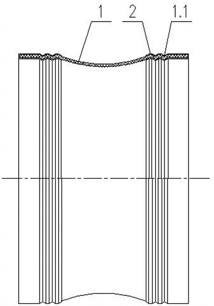
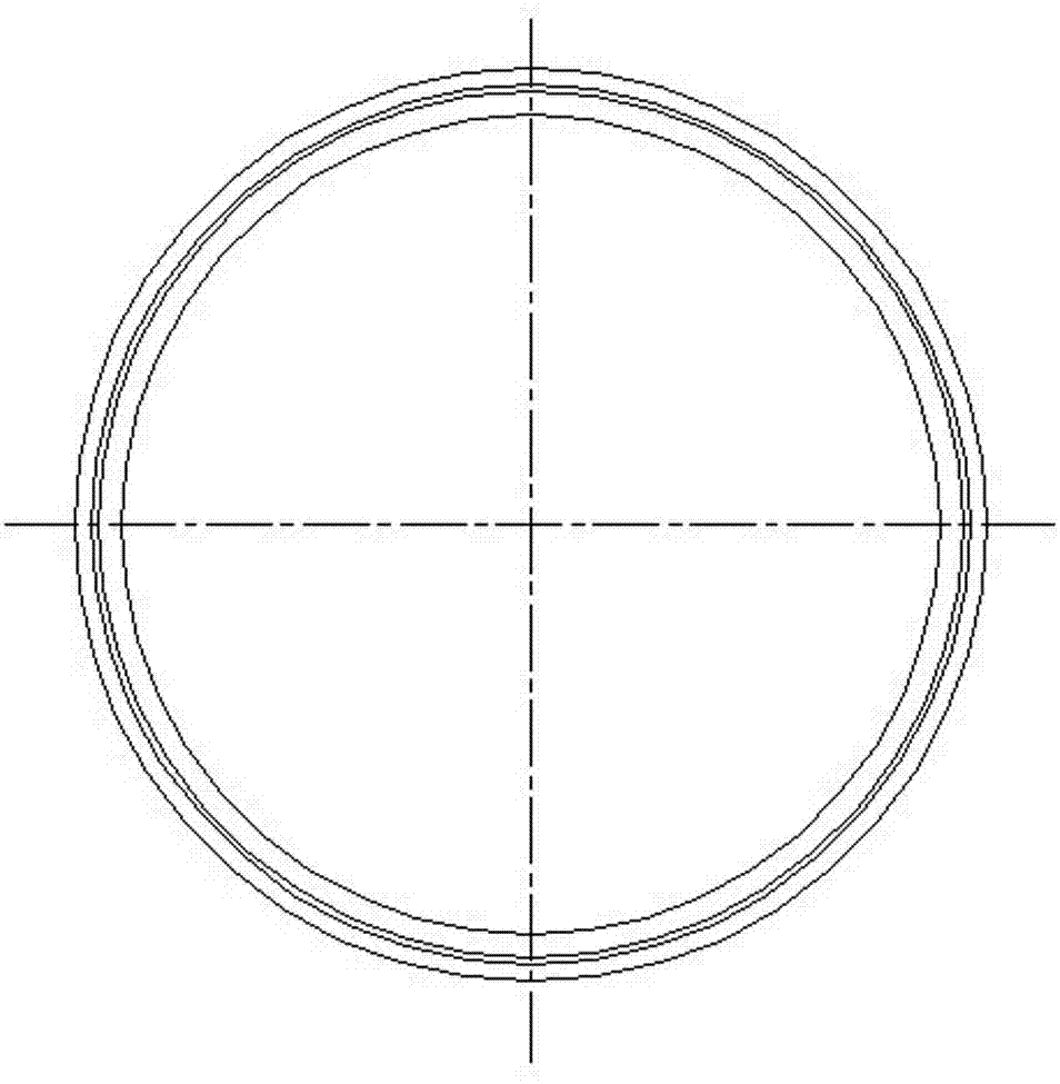
[0015] figure 1 The shown flue anti-corrosion compensator includes hose 1 and connecting pipe 2. The hose 1 is a single-layer thick-walled rubber product, the middle section of the axial section is waist-shaped, and the left and right pipe ends are round and straight pipes. The connecting pipe 2 is a round straight pipe with a jacket structure, and the axial section on one side is a rectangular groove in a lying position, and the opening width of the groove is equal to the wall thickness at both ends of the hose 1 . In this embodiment, due to the small diameter of the supporting flue, the wall thickness of the hose 1 is 5mm, and the whole hose 1 is vulcanized. In order to improve the anti-corrosion performance, the connecting pipe 2 is made of nickel-based alloy steel with good anti-corrosion performance, and the inner surface of the ...


PUM

PropertyMeasurementUnit
thicknessaaaaaaaaaa

Abstract

The invention discloses a flue corrosion prevention compensator used for a flue gas desulphurization system. The flue corrosion prevention compensator comprises a single-layer soft rubber pipe with a thick wall and a nickel-based alloy steel connecting pipe which are vulcanized. The middle section of the axial cross section of the soft pipe shrinks, and the left and right pipe ends are round straight pipes. The connecting pipe is a round straight pipe of a nested structure, the unilateral axial cross section presents a horizontal rectangular groove, and the width of the opening of the groove is equal to the thickness of two end walls of the soft pipe. During assembling, the left and right pipe ends of the soft pipe are respectively sheathed with a connecting pipe, 2-4 grooves are annularly pressed at intervals from the axial middle section of the outer wall of the connecting pipe to the open groove end, and the staggered grooves form a structure connecting with the soft pipe and the connecting pipe in a compact mode. According to the flue corrosion prevention compensator, the strength of the soft pipe is enhanced by the sheathing of the connecting pipe, and the problem that liquid accumulates in the middle section of the soft pipe during the horizontal installation can be avoided. The connecting pipe is made of nickel-based alloy steel, and the connecting pipe is connected with a flue by welding during the installation, and a formed connector has the advantages of high strength, favorable tightness, and reliable and flexible bearing stress compensation or absorption action.

Description

technical field [0001] The invention relates to a pipeline compensator, in particular to a compensator installed in a flue gas desulfurization system, which belongs to the technical field of pipeline safety devices. Background technique [0002] The flue gas transported by the flue gas desulfurization system has a certain temperature. As the temperature of the flue gas transported changes, the flue will inevitably produce corresponding axial displacement or radial displacement and thrust. For the safe operation of the flue gas desulfurization system in the project, it must be A compensator is arranged in the flue to absorb or compensate for deformation caused by internal stress. The flue compensator in the prior art uses double-layered rubber pipe sleeves as compensation elements, and the two ends of the inner and outer sleeves are respectively fitted with metal joints. When installing, the metal joints at both ends are welded into one body with the flue. This structure Sim...

Claims


Application Information

Patent Timeline
Patent Type & Authority Applications(China)
IPC IPC(8): F16L51/00F16L27/107F16L58/18
Inventor 仇庆涛王智峰徐金明
Owner 江苏日升科技实业有限公司
Learn More