Frequency-shift super-resolution microimaging method and device based on evanescent field illumination

A technology of microscopic imaging and evanescent field, applied in measurement devices, analysis materials, material analysis by optical means, etc., can solve the problems of complex system structure, inability to use non-fluorescent samples, cumbersome sample processing, etc., and achieve high resolution. The effect of high precision, high image refresh rate and simple structure

Inactive Publication Date: 2013-04-17
ZHEJIANG UNIV
View PDF9 Cites 35 Cited by
  • Summary
  • Abstract
  • Description
  • Claims
  • Application Information

AI Technical Summary

Problems solved by technology

The electron microscopic imaging technology developed in the 1930s and various non-optical probe scanning microscopic imaging technologies that emerged in the early 1980s have nanometer or even higher resolution capabilities, but they exist to varying degrees. The complex structure of the system, the harsh requirements of the imaging and detection environment, and the cumbersome sample processing are difficult, especially the important optical information of th...

Method used


Image

  • Frequency-shift super-resolution microimaging method and device based on evanescent field illumination
  • Frequency-shift super-resolution microimaging method and device based on evanescent field illumination
  • Frequency-shift super-resolution microimaging method and device based on evanescent field illumination

Examples


Embodiment 1

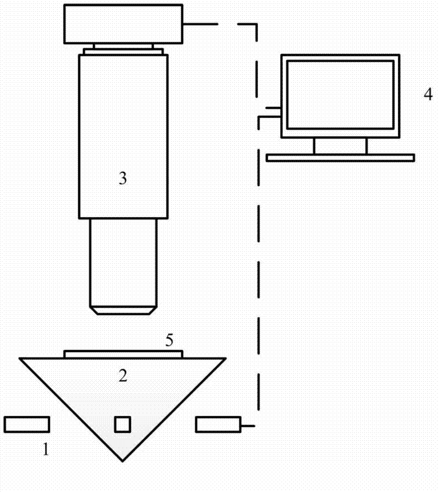
[0066] Such as figure 1 As shown, the device of the frequency-shifting super-resolution microscopic imaging system based on evanescent field illumination includes: a light source group 1, a prism 2, a microscope 3, a computer 4, and a sample 5.

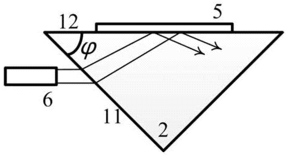
[0067] The light source group 1, the prism 2, the microscope 3 and the sample 5 are located on the coaxial optical path. The incident illumination light emitted by a single sub-light source 6 in the light source group 1 is totally reflected in the prism 2 to produce an evanescent field to illuminate the sample 5 . The generated light intensity distribution is collected and analyzed by the microscope 4 in the far field. Wherein, the incident illumination light refers to visible monochromatic linearly polarized collimated light with the same polarization direction and a wavelength in the range of 380-780 nm.

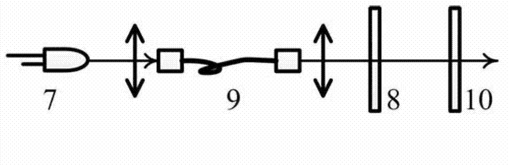
[0068] Fundamentally speaking, the incident illumination light is provided by LED7, in order to meet the requirements of the a...

Embodiment 2

[0086] Except in the specific embodiment of the present inventionfigure 1 In addition to the structural principle diagram provided in , the present invention can also improve the lighting method under the premise of ensuring the same principle.

[0087] like Figure 8 Shown is a structural principle diagram of the improved illumination mode of the frequency-shifting super-resolution microscopic imaging device based on evanescent field illumination of the present invention.

[0088] like Figure 8 As shown, after improving the illumination mode, the device of the frequency-shifting super-resolution microscopic imaging system based on evanescent field illumination includes: a laser light source 13, a vibrating mirror 14, a focusing mirror 15, a reflecting mirror 16, a total reflection objective lens 17, Slide 18, Microscope 3, Computer 4, Sample 5.

[0089] Laser light source 13, vibrating mirror 14, focusing mirror 15, reflecting mirror 16, total reflection objective lens 17,...

Embodiment 3

[0093] In addition to the method described in Embodiment 1 that can improve the illumination method, it can also be improved by using an off-center diaphragm.

[0094] like Figure 9 Shown is a schematic diagram of the structure of the evanescent field illumination-based frequency-shifting super-resolution microscopic imaging device of the present invention after using an eccentric diaphragm to improve the illumination mode.

[0095] like Figure 9 As shown, after improving the illumination mode, the device of the frequency-shifting super-resolution microscopic imaging system based on evanescent field illumination includes: a laser light source 13, an eccentric diaphragm 19, a total reflection objective lens 17, a glass slide 18, and a microscope 3, Computer 4, Sample 5.

[0096] Laser light source 13, eccentric diaphragm 19, total reflection objective lens 17, glass slide 18, microscope 3, and sample 5 are located on the coaxial optical path. The incident illumination ligh...


PUM

PropertyMeasurementUnit
Wavelengthaaaaaaaaaa

Abstract

The invention discloses a frequency-shift super-resolution microimaging method based on evanescent field illumination. The method comprises the steps that 1) incident illumination light obliquely irradiates a substrate medium interface, is totally reflected and generates an evanescent field; 2) the evanescent field is used for illuminating the surface of a sample; a strength image of the surface of the sample is received by a microscope; 3) the strength image is subjected to Fourier transformation; a corresponding frequency spectrum is obtained and is restored; a corresponding frequency spectrum restoring image is obtained; 4) the direction of the incident illumination light is changed for many times around the sample till the direction of the incident illumination light covers 0-360 DEG; frequency spectrum restoring images in different directions are obtained; 5) the frequency spectrum restoring images in the different directions are stacked; a complete high frequency spectrum image is obtained; and 6) the complete high frequency spectrum image is subjected to inverse Fourier transformation; and a super-resolution microscopic image of the observed sample is obtained. The invention further discloses a frequency-shift super-resolution microimaging device based on the evanescent field illumination.

Description

technical field [0001] The invention belongs to the field of microscopic observation and measurement, and in particular relates to a frequency-shifting super-resolution microscopic imaging method and device based on evanescent field illumination. Background technique [0002] Nanotechnology and biotechnology are the fastest-growing and hottest scientific fields in the 21st century. Nanotechnology has a wide range of applications, including imaging, measurement, processing, manipulation, etc. within the scale of 1-100nm. Many important organisms such as glucose, antibodies, viruses, etc. are in this scale range, and the need to study these tiny objects has driven the development of high-resolution microscopy. In turn, the development of super-resolution microscopy has also promoted the progress of the entire life sciences. A major advantage of light microscopy over other microscopy techniques is the ability to study living cells in their natural state. Since the world's fi...

Claims


Application Information

Patent Timeline
IPC IPC(8): G01N21/17G01N21/55
Inventor 刘旭郝翔匡翠方库玉龙李旸晖
Owner ZHEJIANG UNIV
Why Eureka
Try Eureka