Device and method for sludge treatment

A sludge and reactor technology, applied in the oxidation treatment of sludge, sludge treatment, chemical instruments and methods, etc., can solve problems such as low sludge efficiency

Inactive Publication Date: 2013-04-24
湖南清和环保技术有限公司
View PDF2 Cites 11 Cited by
  • Summary
  • Abstract
  • Description
  • Claims
  • Application Information

AI Technical Summary

Problems solved by technology

The efficiency of sludge tre

Method used


Image

  • Device and method for sludge treatment
  • Device and method for sludge treatment
  • Device and method for sludge treatment

Examples


Embodiment 1

[0091] Toner and FeCl with a mass ratio of 80:20 3 Mixing and mixing evenly to obtain an oxidation-guided catalyst;

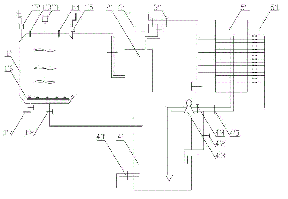
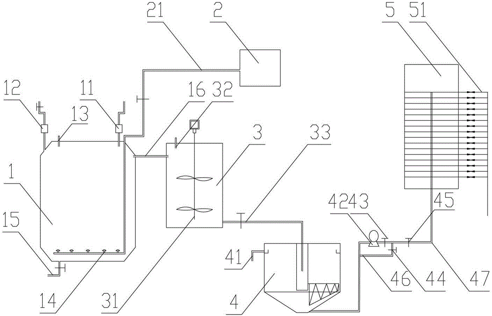
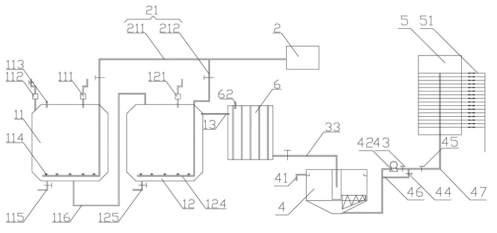
[0092] Pass the sludge to be treated into the membrane rupture reactor through the sludge feed port, add the oxidation-directed catalyst prepared in this embodiment into the membrane rupture reactor through the oxidation reaction material feed port, stir and react, and then pass the ozone The generator feeds ozone into it to carry out redox reaction; the oxidation-guiding catalyst accounts for 5% of the total mass of the dry basis, and the amount of ozone introduced is based on the dry basis mass of the excess sludge: one kilogram of the excess sludge is dry Pass 0.5 grams of ozone into the base;

[0093] The product of the redox reaction obtained is transported in the coagulation reactor, and FeCl containing 50wt% is added thereto through the coagulation agent feeding port. 3 , the coagulation agent of the PAC of 40wt% and the CPAM of 10wt%, the add-on of co...

Embodiment 2

[0096] This embodiment is carried out with reference to the technical scheme of Example 1, the difference is that the oxidation-guiding catalyst in this embodiment is a mixture of activated carbon powder, fly ash, iron formate and aluminum formate with a mass ratio of 35:40:10:15, and the oxidation The addition amount of guide catalyst is 3.5% of the total mass of excess sludge on a dry basis, and the input amount of ozone is based on the dry basis mass of excess sludge: 0.8 grams of ozone equivalent is introduced into one kilogram of this excess sludge on a dry basis;

[0097] The coagulation agent that present embodiment adopts is the FeCl that contains 55wt% 3 , 35wt% PAC and 10wt% CPAM.

Embodiment 3

[0099] This embodiment is carried out with reference to the technical scheme of Example 1, the difference is that the oxidation-guiding catalyst in this embodiment is carbon powder, FeCl 3 and iron acetate, the amount of oxidation-guiding catalyst added is 6.5% of the total mass of the excess sludge on a dry basis, and the amount of ozone introduced is based on the mass of the excess sludge on a dry basis: one kilogram of the excess sludge on a dry basis is passed through Into 0.3 grams of ozone equivalent;

[0100] The coagulation agent that present embodiment adopts is the FeCl that contains 45wt% 3 , 35wt% PAC and 20wt% CPAM.


PUM


Abstract

The invention provides a device and a method for sludge treatment. The device for the sludge treatment comprises a membrane rupture reactor, an ozonator and a coagulation reactor, wherein an aerating apparatus is arranged on the bottom and/or the side wall of the membrane rupture reactor, an outlet of the ozonator is connected with an air inlet of the aerating apparatus, and a feeding outlet of the membrane rupture reactor is connected with a feeding inlet of the coagulation reactor. When the device for the sludge treatment is used for treating sludge, the sludge to be treated, oxidation guiding catalysts and ozone generated by the ozonator have a redox reaction with each other in the membrane rupture reactor, then achieved reaction products are delivered into the coagulation reactor to be through coagulation treatment, then achieved sludge which is through the coagulation treatment is concentrated and filter pressed, and the sludge treatment is completed. When the device for the sludge treatment is used for treating sludge, the redox reaction and the coagulation treatment are carried separately, so that under the condition that all materials are input continuously, the sludge treatment can be carried out continuously, and efficiency of the sludge treatment is improved.

Description

technical field [0001] The invention relates to the technical field of sludge treatment, and more specifically relates to a sludge treatment equipment and method. Background technique [0002] After the sewage is treated, a large amount of residual sludge will be produced. The treatment and disposal of excess sludge is a major problem in sewage biochemical treatment. The basic principle of secondary biochemical treatment of sewage plant sewage is that microorganisms use organic matter in sewage as nutrients for their own metabolism, decompose them, and convert them into CO 2 、H 2 0 and metabolic secretions. The residual secretions produced by the metabolism of microorganisms form excess sludge, which aggregates with scum in sewage and microbial clusters to form excess sludge in sewage plants, which is a secondary product after biochemical treatment of sewage in sewage plants. It has also become urban solid waste. [0003] As we all know, sludge contains a large number o...

Claims


Application Information

Patent Timeline
IPC IPC(8): C02F11/06C02F11/14C02F11/00
Inventor 姜良军
Owner 湖南清和环保技术有限公司
Why Eureka
Try Eureka