
Direct utilization transformation method of converter sludge

A converter sludge, direct technology, applied in furnaces, blast furnaces, furnace types, etc., can solve the problems of high sludge viscosity, easy blockage of sludge pipelines, large floor space, etc., to reduce fuel consumption and eliminate secondary pollution Effect

Inactive Publication Date: 2013-04-24
TIANJIN IRON & STEEL GRP
View PDF1 Cites 3 Cited by
  • Summary
  • Abstract
  • Description
  • Claims
  • Application Information

AI Technical Summary

Problems solved by technology

The disadvantage of this method is that the sludge pipeline is easy to block, the moisture is unstable, which has a great impact on the production process, and the utilization rate of the converter sludge is low, only 30% of the total converter sludge can be used, and most of the remaining sludge can only be used Can take out, serious secondary pollution
[0003] In the direct utilization of converter sludge in the production process, in order to solve the problem of sticky and wet sludge, it is necessary to transport the sludge to the raw material yard for drying, and then transport it for production after the moisture is suitable. The area is large, and there is no extra space for the sludge to dry in the raw material yard, and because the sludge is piled together in groups, even if the external moisture is suitable, the internal moisture is still too large, and the sludge has a high viscosity, which is still difficult to produce. There are often problems with the braised roll, and the production is intermittent and very unstable

Method used


Image

  • Direct utilization transformation method of converter sludge
  • Direct utilization transformation method of converter sludge
  • Direct utilization transformation method of converter sludge

Examples


Embodiment Construction

[0016] In order to further understand the invention content, characteristics and effects of the present invention, the following examples are given, and detailed descriptions are as follows in conjunction with the accompanying drawings:

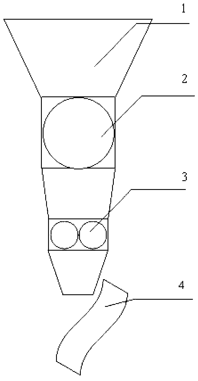
[0017] Such as figure 1 As shown, a conversion equipment for direct utilization of converter sludge includes a silo 1, a round roller feeder 2, a roller crusher 3 and a batching belt 4, a hopper 1, a round roller feeder 2, and a roller crusher 3 are connected sequentially from top to bottom, and the lower part of the roller crusher 3 is provided with a batching belt 4.

[0018] A conversion conversion method for direct utilization of converter sludge, comprising the following steps:

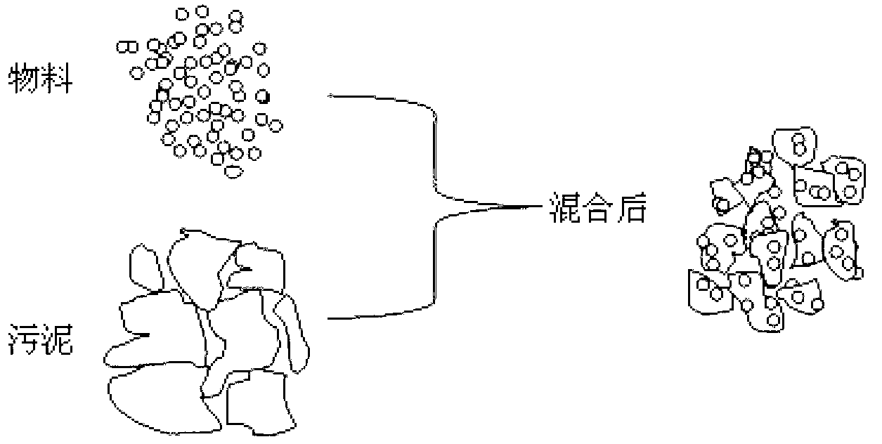
[0019] 1) Add a material that can improve the fluidity of the sludge to the converter sludge in the raw material yard, stir it mechanically, send it to sintering, and store it in the sludge tank. For the effect of mixing sludge and materials, please refer to ...


PUM


Abstract

The invention relates to a direct utilization transformation method of converter sludge. The direct utilization transformation method of the converter sludge comprises (1) adding a material which can improve sludge liquidity into converter sludge in a material store yard, after stirring the converter sludge and the material in a machinery mode, sending the converter sludge to firing, and storing the converter sludge in a sludge holding tank; (2) lifting the converter sludge to a storage bin through a grab crane, and enabling the converter sludge arrive at a roll crushing mill through a round roller feeding machine after the converter sludge comes down from the storage bin; and (3) droping the broken converter sludge into a proportioning belt, and directly participating burdening. The transformation method for the converter sludge direct utilization completely consumes the converter sludge by adding the material which can improve the sludge liquidity into the converter sludge, and enables useful materials to be fully recycled. Iron components in the converter sludge enter into mixed materials, the amount of silica (SiO2) in the converter sludge is small, the amount of tetrafluoroethylene resin (TFe) in sinter is increased, calcium oxide (CaO) is contained in the converter sludge, natural alkalinity is larger than 4.0, and the amount of quicklime in the mixed materials is reduced. The converter sludge contains partial residual carbon, the amount of ferrous oxide (FeO) is high, and the transformation method for the converter sludge direct utilization is beneficial for reducing fuel consumption, and meanwhile eliminates secondary pollution when automobiles outward transport the converter sludge.

Description

technical field [0001] The invention belongs to the technical field of converter sludge utilization, in particular to a conversion method for direct utilization of converter sludge. Background technique [0002] Converter sludge is an iron-containing resource with high iron grade, low w(SiO2) and high utilization value. 30% to 40% of the steelmaking sludge is formed after the filter press is pressed. At present, in the field of iron and steel production, converter sludge directly participates in batching. The original addition method is: make converter sludge into sludge water with a water content of 85% to 90%, and directly add it to the sintering mixture in the cylinder mixer as sintering batching water. The process is simple, no drying is required, and the investment is low. . The disadvantage of this method is that the sludge pipeline is easy to block, the moisture is unstable, which has a great impact on the production process, and the utilization rate of the convert...

Claims


Application Information

Patent Timeline
IPC IPC(8): C22B1/00C21B5/00B09B3/00
Inventor 孙海宁贾佳博许学光王泽海呼建军
Owner TIANJIN IRON & STEEL GRP
Learn More