mems pressure sensor array, its manufacturing method and pressure measurement method

A technology of a pressure sensor and a manufacturing method, which is applied to the fluid pressure measurement using capacitance change, piezoelectric device/electrostrictive device, piezoelectric/electrostrictive/magnetostrictive device, etc., can solve the problem of large measurement error of the pressure sensor , small measurable range, etc.

Active Publication Date: 2016-04-13
SHANGHAI HUAHONG GRACE SEMICON MFG CORP
View PDF6 Cites 1 Cited by
  • Summary
  • Abstract
  • Description
  • Claims
  • Application Information

AI Technical Summary

Problems solved by technology

[0007] However, the cavity of the existing MEMS pressure sensor is generally a certain pressure. When the measured air pressure changes greatly, the measurement error of the pressure sensor will be large, and the measurable range will also be small.

Method used


Image

  • mems pressure sensor array, its manufacturing method and pressure measurement method
  • mems pressure sensor array, its manufacturing method and pressure measurement method
  • mems pressure sensor array, its manufacturing method and pressure measurement method

Examples


Embodiment 1

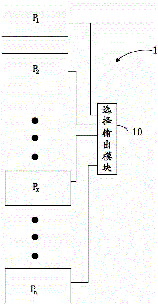
[0092] figure 1 Shown is a simplified diagram of the MEMS pressure sensor array 1 provided in this embodiment. The array 1 consists of:

[0093] n MEMS pressure sensors located on the same chip, n≥2, each of the MEMS pressure sensors has a cavity, and the pressures in the cavities of each MEMS pressure sensor are P 1 ,P 2 …P n , where P 1 ,P 2 ...P n Not equal to each other;

[0094] Select the output module 10 to output the pressure in the cavity as P 1 ,P 2 …P n Among the MEMS pressure sensors, the measured value of the MEMS pressure sensor whose cavity pressure is closest to the environmental pressure P' where the MEMS pressure sensor array is located.

[0095] The following are introduced separately. First, the structure of each MEMS pressure sensor and its fabrication method are introduced.

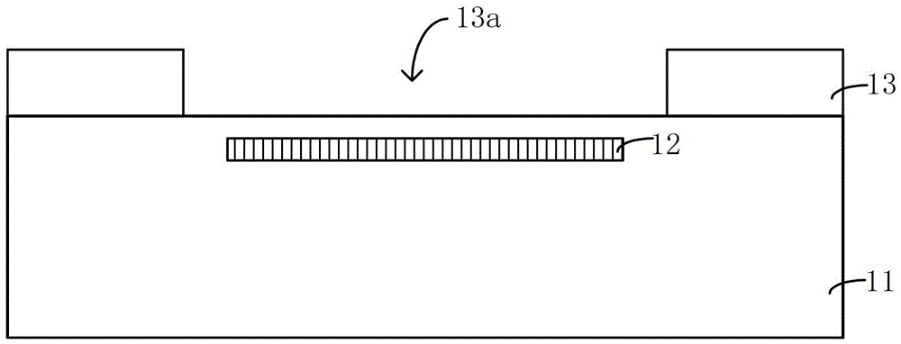
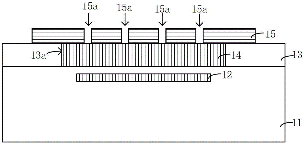
[0096] About the production method: Figure 2 to Figure 4 , Figure 6 to Figure 7 is a cross-sectional view of the structure formed during fabrication, Figure 5 is a ...

Embodiment 2

[0132] refer to Figure 7 As shown, for the single MEMS pressure sensor in the array 1, the manufacturing method needs to reserve an opening 19 for the gas in the cavity 13a to reach a certain pressure. The solution used tends to enter the cavity 13a, causing the sensitive film 15 to stick. In view of the above problems, this embodiment 2 proposes a new MEMS pressure sensor array structure and manufacturing method thereof, so that the solution used for wet cleaning does not directly enter the cavity, thereby reducing the possibility of sensitive film adhesion and improving the production efficiency of MEMS. Yield of the pressure sensor.

[0133] The semiconductor substrate 11, the first electrode 12, the patterned first dielectric layer 13, and the cavity 13a formed in the patterned first dielectric layer 13 in the second embodiment are the same as those in the first embodiment, so the specific process and structure Referring to step S11 and figure 2 shown.

[0134] The f...

Embodiment 3

[0162] The MEMS pressure sensor array provided in the third embodiment, its manufacturing method and pressure measurement method are substantially the same as those in the second embodiment. The difference is: if Figure 20 As shown, the patterned sensitive thin film 15' forming the trench 15b' is disposed on the semiconductor substrate 11 instead of the first dielectric layer 13 in the first embodiment.

[0163] Correspondingly, the method for fabricating the patterned sensitive thin film 15' on the semiconductor substrate 11 includes: first, forming a sacrificial layer on the semiconductor substrate 11; then, etching part of the sacrificial layer until the semiconductor substrate 11 is exposed, leaving The sacrificial layer 14 is used as a support for the sensitive film 15'; afterward, a sensitive film is formed on the sacrificial layer 14 and the semiconductor substrate 11, and part of the sensitive film is etched to form a patterned sensitive film 15'. A trench 15 b ′ is ...


PUM


Abstract

Different from the scheme in which a micro-electromechanical system (MEMS) pressure sensor with a specific pressure in a cavity is adopted for pressure measurement, the invention adopts a plurality of MEMS pressure sensors, namely a MEMS pressure sensor array, with different pressures in cavities located in the same chip, for the pressure measurement. When the outside pressure changes, especially when the pressure changes dramatically, the pressure in a cavity of at least one MEMS pressure sensor is enabled to be possibly close to the pressure of a measured environment, and accurate measurement of the outside pressure is then achieved by means of the good degree of linearity of a sensitive film, near an equilibrium position (the upper pressure and the lower pressure are almost the same), of the MEMS pressure sensor. Furthermore, compared with the pressure sensor with the specific pressure in the cavity, the MEMS pressure sensor array can achieve measurement in a wider pressure range. Based on the MEMS pressure sensor array, the invention further provides a manufacturing method of the MEMS pressure sensor array and a pressure measuring method used for the MEMS pressure sensor array.

Description

technical field [0001] The present invention relates to the field of MEMS (Micro-Electro-Mechanical-System, micro-electro-mechanical system), in particular to a MEMS pressure sensor array and a manufacturing method thereof. In addition, the present invention also relates to a pressure measurement method. Background technique [0002] Since the late 1980s, with the development of micro-electro-mechanical system (Micro-Electro-Mechanical-System, MEMS) technology, various sensors have been miniaturized. [0003] At present, one of the most widely used miniaturized sensors is the MEMS pressure sensor. The MEMS pressure sensor can use the sensitive film in the MEMS to receive external pressure information, and the converted signal is amplified by the processing circuit to measure the specific pressure. pressure information. MEMS pressure sensors are widely used in automotive electronics such as TPMS (tire pressure monitoring system), consumer electronics such as tire pressure ga...

Claims


Application Information

Patent Timeline
Patent Type & Authority Patents(China)
IPC IPC(8): G01L9/12B81B3/00B81C1/00
Inventor 黎坡
Owner SHANGHAI HUAHONG GRACE SEMICON MFG CORP
Why Eureka
Try Eureka