
Crystal position chart establishment method

A technology for establishing methods and location tables, which is applied in image data processing, instruments, calculations, etc., can solve the problems of reduced accuracy, high computational overhead, and prone to accidental deletion, and achieve the effect of improving accuracy and efficiency

Active Publication Date: 2013-04-24
TSINGHUA UNIV
View PDF1 Cites 8 Cited by
  • Summary
  • Abstract
  • Description
  • Claims
  • Application Information

AI Technical Summary

Problems solved by technology

[0003] At present, the methods used to establish the crystal position table mainly include: statistical model method based on mixed Gaussian model, watershed method, self-organizing feature mapping method, principal component analysis method and non-strict registration method based on Fourier template; among them, based on mixed Gaussian model The method uses the average point deletion method to remove the identified points, which is prone to mistaken deletion; the watershed method is sensitive to the pre-processing of the image, and the results of the pre-processing of the image have a great influence on the later segmentation; both the self-organizing feature map and the principal component analysis method require training sets. , if there is a large difference between the training set and the image to be segmented, the accuracy is likely to decrease; the method based on the Fourier template needs to estimate the template empirically, and its application is limited
Although the above-mentioned methods for establishing the crystal position table have their own applicability, because they are sensitive to the empirical parameters of the image processing method or have high computational overhead, a simple and stable method for establishing the crystal position table is needed

Method used


Image

  • Crystal position chart establishment method
  • Crystal position chart establishment method
  • Crystal position chart establishment method

Examples


Embodiment Construction

[0018] The present invention will be described in detail below in conjunction with the accompanying drawings and embodiments.

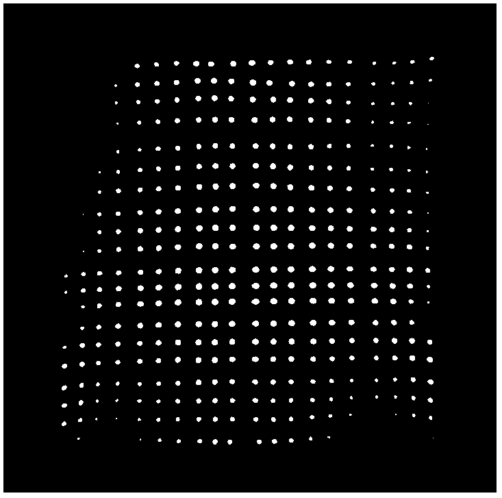
[0019] Such as figure 1 As shown, in the positron emission tomography imaging system, in order to obtain the crystal position table, first, an annihilation photon source continuously emits photons, and the two-dimensional crystal detector continuously receives photons, and finally obtains a two-dimensional position scatter diagram, and the two-dimensional position scatter point Each pixel in the graph (such as figure 1 White dots shown in ) record the number of incident gamma photon events detected at each coordinate position.

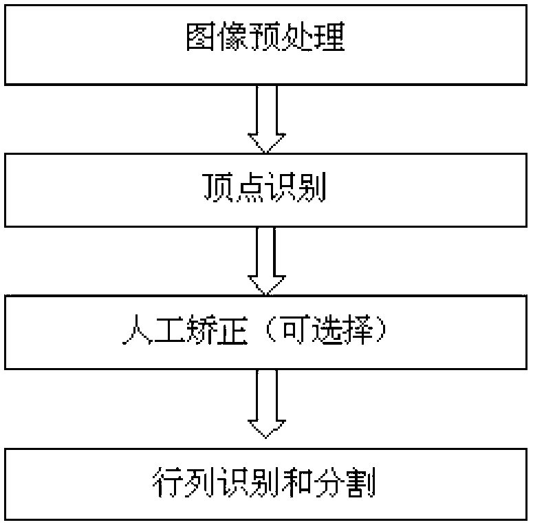
[0020] Such as figure 2 As shown, the crystal position table establishment method of the present invention comprises the following steps:

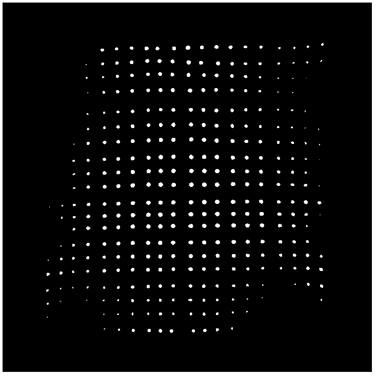
[0021] 1. Using the morphological method to preprocess the two-dimensional position scatter diagram, including the following steps:

[0022] 1) Read the two-dimensional position scatt...


PUM


Abstract

The invention relates to a crystal position chart establishment method which comprises following steps of (1) utilizing a morphological method to conduct preprocessing for a two-dimensional position scatter diagram; (2) distinguishing top points of the two-dimensional position scatter diagram; (3) judging correctness of the top points which are distinguished in the step (2), if the top points which are distinguished in the step (2) are all correct, the top points enter into a step (4) and the top points which are distinguished in the step (2) have errors, the mistaken top points are corrected manually and then enter into the step (4); (4) conducting classification for the top points according to lines; (5) completing calculating of all middle points according to coordinates of an upper top point, a lower top point, a left top point and a right top point, the upper top point, the lower top point, the left top joint and the right top joint are sequentially adjacent in each adjacent two lines; (6) respectively conducting curve fitting for all the middle points in a line and column mode, and completing partitioning of the two-dimensional position scatter diagram. The crystal position chart establishment method can be widely applied to the crystal position chart establishing process of a positive electron emission tomography system.

Description

technical field [0001] The invention relates to a method for establishing a crystal position table, in particular to a method for establishing a crystal position table suitable for a positron emission tomography imaging system. Background technique [0002] Positron emission tomography system is an advanced medical device that uses imaging technology to study human heart and brain metabolism and receptor function at the molecular level. Positron emission tomography can reflect the metabolism and physiological activities of tissues and cells, and has high sensitivity. It has guiding significance for the diagnosis of heart, brain and tumor diseases in clinical practice. In positron emission tomography systems, crystal position tables are used to map the positions of photons of annihilation events to corresponding crystals in a two-dimensional crystal detector. The accuracy of the crystal position table affects the performance of the entire positron emission tomography imaging...

Claims


Application Information

Patent Timeline
IPC IPC(8): G06T7/00G06T5/00
Inventor 张辉王新增胡广书
Owner TSINGHUA UNIV
Learn More