Electric field accelerating type gas compressor

A gas compressor, accelerated technology, applied in the field of compression, can solve problems affecting the safety of the compressor, complex system control, and affecting heat transfer performance, etc., to achieve the effects of improving operating efficiency, stable output pressure, and increasing life

Active Publication Date: 2013-04-24
GUANGDONG EUROKLIMAT AIR CONDITIONING & REFRIGERATION
View PDF4 Cites 0 Cited by
  • Summary
  • Abstract
  • Description
  • Claims
  • Application Information

AI Technical Summary

Problems solved by technology

[0002] Existing compressors have speed type and volume type and other forms, among which speed type is divided into centrifugal type and axial flow type, and volume type is divided into piston type, screw type, scroll type, rotor type and other compressors. Their The structure is made into a semi-closed or fully closed type, (there are also open types, but there are disadvantages of refrigerant leakage). The power source is the electric motor, which is immersed in the entire compressed gas
Due to the limitation of the motor temperature rise of the compressor, the exhaust temperature of the compressor is generally controlled below 110 degrees Celsius, which limits the working range of the compressor. At the same time, due to the rotating parts, there are mechanical wear problems and there will be a rotation gap. , as the pressure increases, the gap leakage will also increase, which limits the working efficiency and working range of the compressor
In addition, the traditional compressor has rotating parts and needs lubricating oil. Once the compressor is short of oil, it will immediately affect the safety of the compressor. Therefore, in order to ensure that the compressor is always not short of oil, it is necessary to design an oil circulation system. At the same time, there is oil in the system. , affects the heat transfer performance, and also complicates the system control

Method used


Image

  • Electric field accelerating type gas compressor

Examples


Embodiment Construction

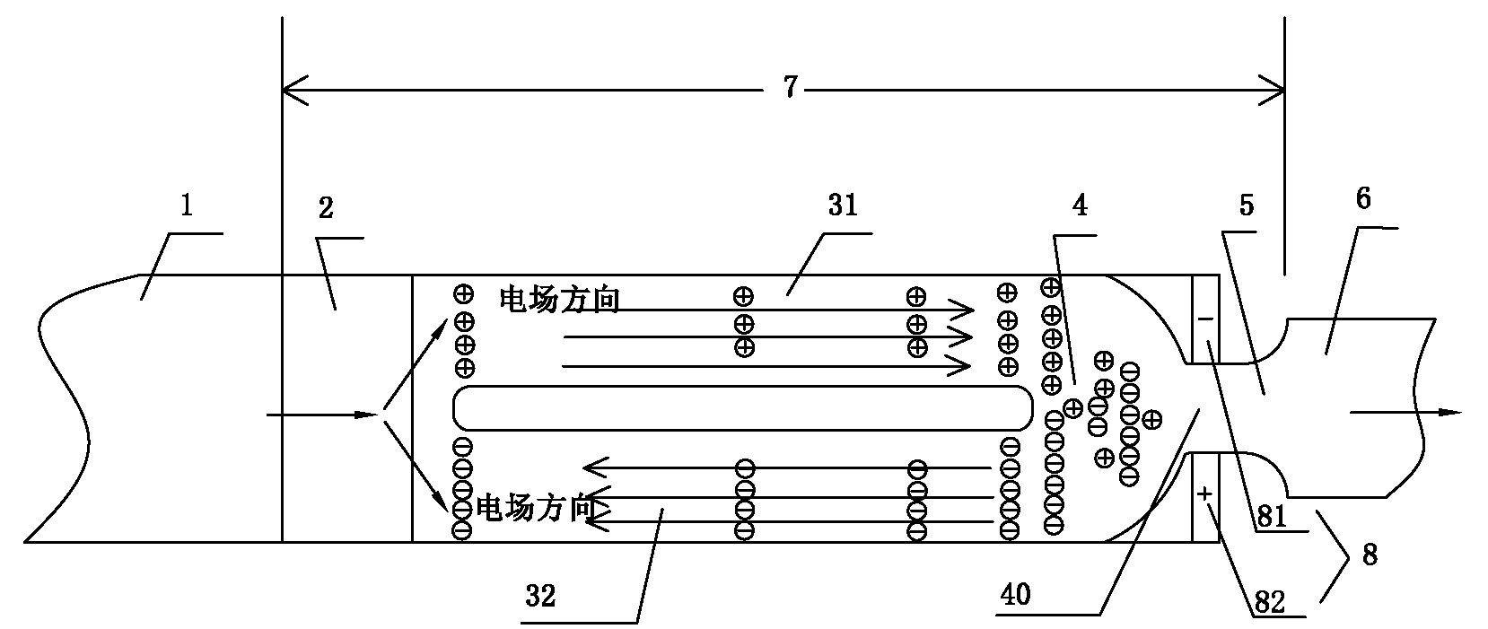
[0012] Electric field accelerated gas compressors such as figure 1 , the suction pipe 1, the compression area 7 and the exhaust pipe 6 are sequentially connected from input to output, the compression area 7 specifically: includes the ionization area 2 connected to the suction pipe 1, and the ionization area 2 is divided into two parallel branches Roads 31 , 32 , two branch roads 31 , 32 merge to form a confluence area 4 , and the confluence area 4 is output to the exhaust pipe 6 via a diffuser pipe 5 . The end section 40 of the confluence area 4 is narrowed in the middle, and an electrified body 8 is installed on the periphery of the end section 40 of the confluence area 4. The negatively charged area 81 is aligned with the first branch 31, and the positively charged area 82 is aligned with the second branch. The branch 32 forms an electric field applied to the two branches 31, 32, the electric field of the first branch 31 points to the output end, and the electric field of th...


PUM


Abstract

Disclosed is an electric field accelerating type gas compressor. A compression zone particularly comprises an ionization zone which is connected to an air suction pipe. Gas is produced positively charged particles and negatively charged particles by ionization in the ionization zone. The ionization is divided into two paratactic branches, and electric field is applied. A first branch electric field points an output end, and a second branch electric field points an input end, so that the positively charged particles are enabled to enter the first branch and accelerate under the effect of electric field force, the negatively charged particles are enabled to enter the second branch and accelerate, and the two branches are converged and form a converged zone. The accelerated positively charged particles and the negatively charged particles neutralize with power-lossing, and speed is maintained. The converged zone is outputted to an air exhaust pipe through a diffuser pipe. According to the electric field accelerating type gas compressor, fatal defects of physical deterioration, clearance leakage and the like are eliminated, service life of the compressor can be prolonged, design structure is simple, opening of compressor interior is not needed when the compressor is repaired, cost is saved, lubricant oil adding is not needed, operating efficiency of the system is improved, and meanwhile safe reliability of the system is improved.

Description

technical field [0001] The invention relates to a gas compressor, which can be applied to compression fields such as air conditioning, refrigeration, and chemical industry. Background technique [0002] Existing compressors have speed type and volume type and other forms, among which speed type is divided into centrifugal type and axial flow type, and volume type is divided into piston type, screw type, scroll type, rotor type and other compressors. The structure is made into a semi-closed or fully closed type, (there are also open types, but there are disadvantages of refrigerant leakage). The power source is the electric motor, which is immersed in the entire compressed gas. Due to the limitation of the motor temperature rise of the compressor, the exhaust temperature of the compressor is generally controlled below 110 degrees Celsius, which limits the working range of the compressor. At the same time, due to the rotating parts, there are mechanical wear problems and there...

Claims


Application Information

Patent Timeline
Patent Type & Authority Applications(China)
IPC IPC(8): H01J41/12
Inventor 陈军林成祥张平罗晓燕
Owner GUANGDONG EUROKLIMAT AIR CONDITIONING & REFRIGERATION
Why Eureka
Try Eureka