High gain and high efficiency planar antenna

A flat-panel antenna, high-efficiency technology, applied in slot antennas, resonant antennas, circuits, etc., can solve the problems of high gain, small size, complex design and debugging, etc., and achieve high gain, large bandwidth, and compact structure.

Inactive Publication Date: 2013-04-24
SHANDONG GUOWEI SATELLITE COMM
View PDF11 Cites 2 Cited by
  • Summary
  • Abstract
  • Description
  • Claims
  • Application Information

AI Technical Summary

Problems solved by technology

The panel antenna described in this patent is smaller in size and higher in gain than ordinary antennas, but the design and debugging are complicated

Method used


Image

  • High gain and high efficiency planar antenna
  • High gain and high efficiency planar antenna
  • High gain and high efficiency planar antenna

Examples


Embodiment

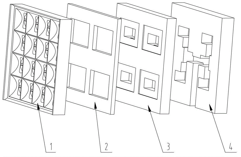
[0030] A high-gain and high-efficiency planar antenna, including a feeding layer 4, a coupling layer 3, a resonant cavity layer 2, and a radiation layer 1 arranged in sequence according to the electromagnetic wave propagation direction; the radiation layer 1 includes a plurality of radiation units, each radiation The unit includes a special-shaped radiator 5 and a radiation slot 6 opposite to the special-shaped radiator 5; the special-shaped radiator 5 includes a hyperboloid structure part 13 and a conical barrel structure part 14, and the function of the hyperboloid is: x(t) =0,y(t)=t, t∈(-22mm, 22mm), a=18, b=10; the conical barrel structure part includes a side wall 14 and a bottom surface 16, and the included angle between the side wall 14 and the bottom surface 15 is α=19.7°. The apex of the hyperboloid is tangent to the bottom surface 16 of the cone barrel, and the straight line 17 formed by the apex of the hyperboloid coincides with the diameter of the bottom surface 1...


PUM


Abstract

The invention discloses a high gain and high efficiency planar antenna. The high gain and high efficiency planar antenna comprises a feed layer, a coupling layer, a resonant cavity layer and a radiation layer, wherein the feed layer, the coupling layer, the resonant cavity layer and the radiation layer are sequentially arranged according to the electromagnetic wave propagation direction. The radiation layer comprises a plurality of radiation units and special-shaped radiators, wherein the special-shaped radiators are in a novel structure. Electromagnetic waves are radiated towards space by the special-shaped radiators, each special-shaped radiator is formed by a double-curved-surface cut conical barrel, and therefore the electromagnetic waves can be radiated out along the double-curved-surface structure portions of the special-shaped radiators in a uniform amplitude and inphase mode, and the double-curved-surface structure portions of the special-shaped radiators can weaken mutual electromagnetic interference of adjacent special-shaped radiators. The high gain and high efficiency planar antenna breaks thinking patterns of an existing planar antenna design structure, the planet planar antenna unique in structure is designed through a great deal of experimental simulation, and therefore the whole planar antenna is compact in structure, low in section and high in gain, and meets existing planet planar antenna technical demands, namely high efficiency, large band width and small size, and efficiency of the planar antenna can be improved by more than 85%.

Description

technical field [0001] The invention relates to a high-gain and high-efficiency panel antenna, which belongs to the technical field of satellite communication panel antennas. Background technique [0002] Panel antennas have the advantages of light weight, small size, less space, small wind resistance, and high efficiency. Compared with other forms of antennas such as parabolic antennas, panel antennas have higher efficiency, higher gain, and smaller size. However, the current panel antenna The efficiency is between 75% and 80%, and it is difficult to break through the efficiency of 80% from the technical level to achieve higher efficiency. [0003] The existing planar antennas have various structures, but most of them only meet the technical conditions of short-distance communication: [0004] For example, Chinese patent application CN101752655A discloses a flat panel antenna, which includes a substrate, multiple antenna bodies and a metal layer. The multiple antenna bodi...

Claims


Application Information

Patent Timeline
Patent Type & Authority Applications(China)
IPC IPC(8): H01Q1/38H01Q9/04H01Q13/10
Inventor 唐文成薛丽丽郭希涛刘冰
Owner SHANDONG GUOWEI SATELLITE COMM
Why Eureka
Try Eureka