Voltage-multiplying DC converter based on charge pump capacitor

A technology of DC converter and charge pump, which is applied in the direction of converting DC power input to DC power output, adjusting electrical variables, and output power conversion devices, which can solve the problem of increased overall volume, increased cost, and increased conduction loss, etc. problem, to achieve the effect of simple circuit topology, lower requirements for withstand voltage level, and reduced conduction loss

Inactive Publication Date: 2013-04-24
SHANGHAI UNIVERSITY OF ELECTRIC POWER
View PDF4 Cites 15 Cited by
  • Summary
  • Abstract
  • Description
  • Claims
  • Application Information

AI Technical Summary

Problems solved by technology

However, this method will increase the conduction loss due to the long conduction time required by the switch, increase the input current ripple, and reduce the conversion efficiency of the circuit, and the switching frequency will also be limited in many aspects in practical applications.
[0004] 2. The structure of the multi-stage connection method makes the topology of the main circuit more complex, thus increasing the manufacturing cost. On the other hand, the multi-stage connection also increases the difficulty of control and reduces the circuit efficiency.
[0005] 3. The use of transformers and coupled inductors will easily increase the overall volume. In addition, in order to obtain a suitable gain, the design of the number of

Method used


Image

  • Voltage-multiplying DC converter based on charge pump capacitor
  • Voltage-multiplying DC converter based on charge pump capacitor
  • Voltage-multiplying DC converter based on charge pump capacitor

Examples


Embodiment 1

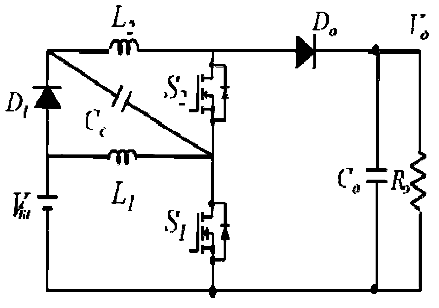
[0034] like figure 2 As shown, a voltage doubler DC converter based on charge pump capacitors, including an input power supply V in , main switch circuit, freewheeling diode D o , output capacitor C o and load R o , the input power supply V in Connected to the input terminal of the main switch loop, the freewheeling diode D o and the output capacitor C o After connecting in series with the output terminal of the main switch loop, the load R o with the output capacitor C o In parallel, the main switching loop includes the input diode D 1 , the first inductance L 1 , the second inductance L 2 , charge pump capacitor C c , the first main switch S 1 and the second main switch S 2 , the first main switch S 1 One end is connected to the input power supply V in the negative pole and the output capacitor C o , and the other ends are respectively connected to the first inductor L 1 , charge pump capacitor C c and the second main switch S 2 , the first inductance L 1...

Embodiment 2

[0041] like Figure 7 As shown, a voltage doubler DC converter based on charge pump capacitance, this embodiment is basically the same as Embodiment 1, the difference is that the DC converter of this embodiment also includes an auxiliary power supply nV in , the auxiliary supply nV in The anode of the input diode D 1 Anode connection, auxiliary supply nV in The negative poles are respectively connected to the input power supply V in positive pole and the first inductor L 1 . The voltage value of the auxiliary power supply is n times the voltage value of the input power supply.

[0042] The working state of the DC converter in this embodiment within one switching cycle can be divided into two stages;

[0043] Stage 1: S 1 , S 2 While on, L 1 and L 2 and the charge pump capacitor C c Entering the energy storage stage, L 1 through the input voltage V in charging, L 2 By input voltage (1+n)V in Charging, while input voltage (1+n)V in to the charge pump capacitor C ...


PUM


Abstract

The invention relates to a voltage-multiplying DC converter based on a charge pump capacitor. The voltage-multiplying DC converter comprises an input power supply, a main switch loop, a freewheel diode, an output capacitor and a load, wherein the input power supply is connected with the input end of the main switch loop; and the freewheel diode is connected with the output end of the main switch loop after serially connecting the output capacitor. The main switch loop includes an input diode, a first inductor, a second inductor, a charge pump capacitor, a first main switch and a second switch, wherein one end of the first main switch is respectively connected with the negative electrode of the input power supply and the output capacitor, and the other end is respectively connected with the first inductor, the charge pump capacitor and the second main switch; the first inductor is respectively connected with the positive electrode of the input power supply and the anode of the input diode; the charge pump capacitor is respectively connected with the cathode of the input diode and the second inductor; and the second main switch is respectively connected with the second inductor and the freewheel diode. In comparison with the prior art, the voltage-multiplying DC converter provided by the invention has the advantages of improved voltage gain, less conduction loss, low cost, simple circuit structure and so on.

Description

technical field [0001] The invention relates to a direct current converter, in particular to a voltage doubling type direct current converter based on a charge pump capacitor. Background technique [0002] With the rapid development of new energy in recent years, distributed power generation systems using green energy as primary power sources have also attracted more and more attention. However, due to the low input value of photovoltaic power generation and fuel cell power generation systems, a step-up DC converter is required at the front end of the system to increase the low voltage emitted by the new energy. However, how to design a converter with a higher boost ratio at low cost and high efficiency has become a very important issue. Traditional DC boost converters such as figure 1 As shown, the prior art mainly has the following disadvantages: [0003] 1. In order to achieve high gain, for traditional DC boost converters, the method of increasing the switching duty c...

Claims


Application Information

Patent Timeline
IPC IPC(8): H02M3/155
Inventor 赵晋斌梁晓霞屈克庆
Owner SHANGHAI UNIVERSITY OF ELECTRIC POWER
Why Eureka
Try Eureka