Twin-wire electrogas welding water-cooled welding torch

A technology of gas-electric vertical welding and welding torch, which is applied in the direction of arc welding equipment, electrode characteristics, welding equipment, etc. It can solve the problems of not disclosing the welding torch structure, increasing the amount of welding wire deposition, and increasing the input of welding heat, so as to reduce the amount of welding wire , fast welding speed, reduce the effect of welding heat input

Inactive Publication Date: 2013-05-01
刘振英
View PDF6 Cites 10 Cited by
  • Summary
  • Abstract
  • Description
  • Claims
  • Application Information

AI Technical Summary

Problems solved by technology

[0005] However, this patent does not disclose the structure of the welding torch used. For vertical gas-electric vertical welding, the structure of the welding torch is very important. This welding method is to vertically place the two steel plates to be welded with a fixture, leaving a certain gap between the two plates. The welding torch is located in the gap. Driven by the machine head, it moves back and forth along the thickness direction and swings on both sides in the gap to ensure that the side wall of the weld seam is fully fused with the welding pool. After welding one layer, the machine head moves up and then welds The second layer, similar to narrow gap welding, the welding torch of narrow gap welding moves upward along the thickness of the plate, while the welding torch of vertical gas-electric vertical welding moves upward along the length of the weld
Therefore, the width of the part of the welding torch located in the weld seam is required to be very narrow, otherwise the gap between the two plates will be increased. Enlarging the gap will inevitably increase the deposition amount of welding wire, reduce production efficiency, and increase welding heat input, and the welding torch needs Working for a long time under high temperature welding

Method used


Image

  • Twin-wire electrogas welding water-cooled welding torch
  • Twin-wire electrogas welding water-cooled welding torch
  • Twin-wire electrogas welding water-cooled welding torch

Examples


Embodiment Construction

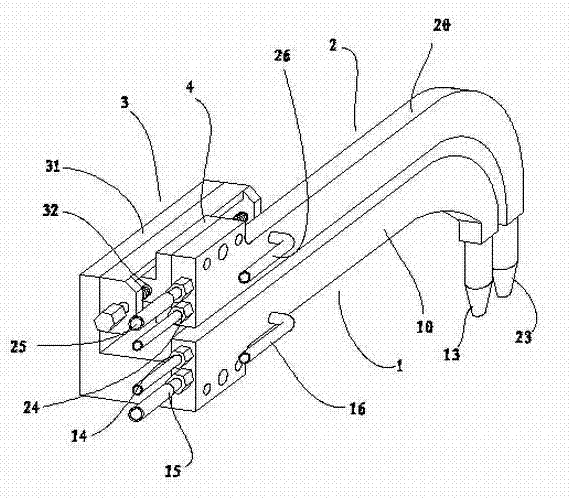
[0025] see figure 1 As shown, the double-wire gas-electric vertical welding water-cooled torch of the preferred embodiment of the present invention includes two mutually insulated first water-cooled torches 1, the second water-cooled torch 2 and the adjusting device 3 of the welding wire spacing, wherein the adjustment of the welding wire spacing The device 3 includes a base 31 and a screw nut 32 mechanism arranged on the base 31, the first welding torch 1 is fixed to the base 3, and the second welding torch 2 is connected to the screw through a fixing plate 4. In the nut mechanism, the nut is fixed, and the second welding torch 2 is located on the upper part of the first welding torch 1, and the two are in the same vertical plane. The front and back distance of the second welding torch contact tip can be adjusted by rotating the screw rod to meet the needs of vertical welding of different plates and different thicknesses.

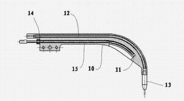
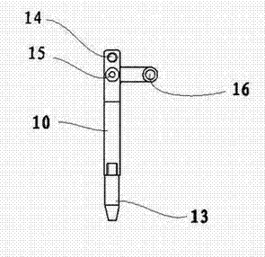
[0026] Such as figure 2 , image 3 , Figure 4 ...


PUM


Abstract

The invention relates to a welding torch for arc welding, in particular to a twin-wire electrogas welding water-cooled welding torch, which comprises a first water-cooled welding torch and a second water-cooled welding torch which are mutually insulated, and an adjusting device for a distance between welding wires. The twin-wire electrogas welding water-cooled welding torch is characterized in that the adjusting device for the distance between the welding wires comprises a substrate and a feed screw nut mechanism arranged on the substrate; the first welding torch is fixed with the substrate; the second welding torch is fixed with a nut of the feed screw nut mechanism through a fixing plate; and the second welding torch is positioned above the first welding torch. The distance between the two welding torches is adjustable, an adjusting range for a welding condition is widened, proper current, voltage, welding speed and distance between the welding wires can be selected according to the thickness and materials of plates to be welded, and high quality welding lines are efficiently completed.

Description

technical field [0001] The invention relates to a welding torch for arc welding, in particular to a water-cooled welding torch for double-wire gas-electric vertical welding. Background technique [0002] The vertical gas-electric vertical welding method based on the metal gas shielded welding technology is an efficient welding method specially used for welding vertical seams between flat workpieces, and is suitable for heavy metal structures, such as shipbuilding, containers, large oil storage tanks, and blast furnace shells etc., the thickness of the welded plate can reach more than 200mm. However, the biggest problem of these vertical gas-electric vertical welding methods is that the welding heat input is high, and the welding heat input is proportional to the thickness of the plate. The increase of heat input with the increase of plate thickness will reduce the crystallization speed of the weld metal, resulting in welding Coarse grains in seams and heat-affected zones le...

Claims


Application Information

Patent Timeline
Patent Type & Authority Applications(China)
IPC IPC(8): B23K9/28B23K9/173
Inventor 刘振英
Owner 刘振英
Why Eureka
Try Eureka