
Rolling flexible pre-stressed auxiliary guide rail device for heavy machine tool

A technology for auxiliary guides and heavy-duty lathes, used in large fixed members, metal processing machinery parts, metal processing equipment, etc., can solve the problems of poor rigidity of auxiliary guide rails, uncontrollable size of finishing operations, difficult implementation, etc. Linear accuracy requirements, the effect of eliminating twisting and crawling, and avoiding the phenomenon of rocking

Inactive Publication Date: 2013-05-01
天津市天重江天重工有限公司
View PDF6 Cites 0 Cited by
  • Summary
  • Abstract
  • Description
  • Claims
  • Application Information

AI Technical Summary

Problems solved by technology

In the CAM transformation of the heavy-duty horizontal car with three guide rails, in order to eliminate the fitting gap between the Z-axis gear and the rack, an anti-backlash gearbox and a drive servo motor are installed at the original tool box position at the lower part of the outer large carriage of the tool holder guide rail. The outward movement of the upper Z-axis drive system, the track lubrication system, the addition of the operator’s walking platform, the safety guardrail, and the change of the tower tool table to the frame tool frame caused the center of gravity of the large pallet to move outward; resulting in the large pallet and the tailstock tool rest The pressure plate of the shared guide rail accelerates wear, and the outer guide rail of the large carriage wears out with the aluminum lining plate, forming a warping phenomenon with the outer guide rail as the fulcrum. The operator moves on the walking table to reflect the change of processing traces and dimensions on the workpiece, and the size of the finishing operation Uncontrollable, affecting product quality
At present, the domestic industry uses rigid auxiliary guide rails to alleviate the warping phenomenon, but it is difficult to implement. It is required that the auxiliary guide rails have good consistency with the machine tool guide rails, and the adjustment is very difficult. Due to the poor stiffness of the auxiliary guide rail itself, the stability is low. twisting and crawling

Method used


Image

  • Rolling flexible pre-stressed auxiliary guide rail device for heavy machine tool
  • Rolling flexible pre-stressed auxiliary guide rail device for heavy machine tool
  • Rolling flexible pre-stressed auxiliary guide rail device for heavy machine tool

Examples


Embodiment Construction

[0013] In order to further understand the invention content, characteristics and effects of the present invention, the following examples are given, and detailed descriptions are as follows in conjunction with the accompanying drawings:

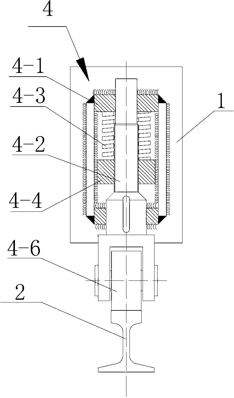
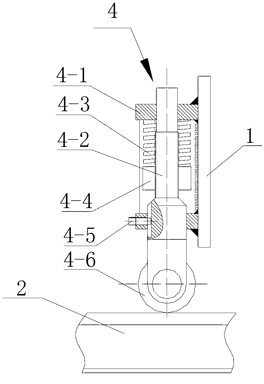
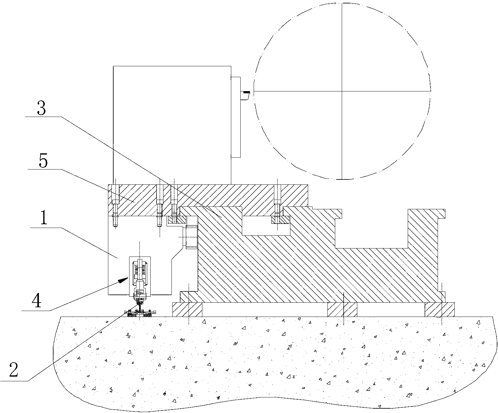
[0014] see Figure 1 to Figure 3 , a rolling flexible prestressed auxiliary guide rail device for a heavy-duty lathe, the auxiliary guide rail device includes an auxiliary guide rail 2 installed outside the lower part of the lathe anti-backlash gear box 1, the auxiliary guide rail 2 is as long as the machine tool guide rail 3, and the anti-backlash gear box Elastic support components 4 are installed on the left and right sides.

[0015] In the above structure, the elastic support assembly 4 includes a cage 4-1 connected to the anti-backlash gear box, a wheel shaft 4-2 is rotated on the cage, and a spring is sleeved on the wheel shaft 4-2 in the cage 4-3, the lower end of the spring 4-3 is screwed with an adjusting nut 4-4, and the lower end ...


PUM


Abstract

The invention relates to a rolling flexible pre-stressed auxiliary guide rail device for a heavy machine tool. The rolling flexible pre-stressed auxiliary guide rail device is characterized by comprising an auxiliary guide rail arranged on the outer side of the lower part of an anti-backlash gear box of the machine tool, wherein the length of the auxiliary guide rail is equal to that of a machine tool guide rail; and elastic support assemblies are arranged on the left and right sides of the anti-backlash gear box. In the structure, pre-supporting force is generated through the elastic support assemblies, so that the gravity center of a large supporting plate of the machine tool falls between the two guide rails, closes to one third part of the auxiliary guide rail and is matched with roller support, so that torsion and climbing phenomena are eliminated basically; and furthermore, the phenomenon of warping is avoided effectively, and the running stability of equipment is enhanced.

Description

technical field [0001] The invention belongs to the technical field of heavy-duty lathe manufacturing, in particular to a rolling flexible prestressed auxiliary guide rail device for heavy-duty lathes. Background technique [0002] The traditional heavy-duty sleeping car is divided into three guide rails, four guide rails, five guide rails and so on. In the CAM transformation of the heavy-duty horizontal car with three guide rails, in order to eliminate the fitting gap between the Z-axis gear and the rack, an anti-backlash gearbox and a drive servo motor are installed at the original tool box position at the lower part of the outer large carriage of the tool holder guide rail. The outward movement of the upper Z-axis drive system, the track lubrication system, the addition of the operator’s walking platform, the safety guardrail, and the change of the tower tool table to the frame tool frame caused the center of gravity of the large pallet to move outward; resulting in the l...

Claims


Application Information

Patent Timeline
Patent Type & Authority Applications(China)
IPC IPC(8): B23Q1/01
Inventor 蔡春男梁学科
Owner 天津市天重江天重工有限公司
Learn More