
Brake-type liquid viscosity transmission device
A transmission device and fluid-viscous technology, applied in the combination of couplings and brakes, mechanical equipment, etc., can solve the problems of large space occupation, difficult coordination control, complex transmission structure chain, etc., to achieve improved speed regulation and ingenious conception Effect
- Summary
- Abstract
- Description
- Claims
- Application Information
AI Technical Summary
Problems solved by technology
Method used
Image

Examples
Embodiment approach
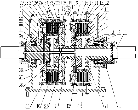
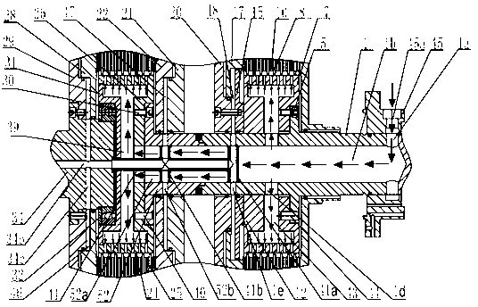
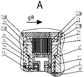
[0043] As the first embodiment of the present invention, see figure 1 with figure 2 , The brake type hydraulic viscous transmission device of the present invention is mainly composed of a box body, a speed regulating mechanism and a braking mechanism. Among them, the speed regulating mechanism includes the first shaft 52, the second shaft 34, the second shaft through cover 35, the active friction plate 25, the passive friction plate 24, the passive drum 27, the passive disc 29, the first piston cylinder and the first control oil The oil pipe 41a; the brake mechanism includes the brake shaft 1, the brake shaft through cover 45, the dynamic friction plate 8, the static friction plate 10, the brake drum 14, the brake disc 20 and the second piston cylinder. see figure 2 with Image 6 , the second shaft 34 is provided with the first radial oil passage 34a, the second radial oil passage 34c and the first axial oil passage 34b which communicate with each other; the first shaft 5...
PUM
 Abstract
Description
Claims
Application Information