Lubricating agent, friction pair and method for controlling friction coefficient between friction pair

A friction coefficient and lubricant technology, applied in the field of lubricants, friction pairs and the friction coefficient control between friction pairs, can solve the problems of metal friction parts prone to corrosion, easily corroded, aqueous solution precipitation reaction, etc., to achieve electrochemical stability The effect of wide potential window, stable electrochemical properties, and large load speed range

Inactive Publication Date: 2013-05-01
TSINGHUA UNIV
View PDF5 Cites 9 Cited by
  • Summary
  • Abstract
  • Description
  • Claims
  • Application Information

AI Technical Summary

Problems solved by technology

However, the current research on active friction control technology still faces many problems. For example, when the lubricant used is an aqueous solution, metal friction parts are easily corroded in it; It is continuously corroded under electrochemical action; when the applied voltage is as high as 10-20V, it will cause hydrogen evolution reaction in

Method used


Image

  • Lubricating agent, friction pair and method for controlling friction coefficient between friction pair
  • Lubricating agent, friction pair and method for controlling friction coefficient between friction pair
  • Lubricating agent, friction pair and method for controlling friction coefficient between friction pair

Examples


Example Embodiment

[0057] among them, figure 1 An example of the above-mentioned device for implementing the method for controlling the coefficient of friction between friction pairs of the present invention is given, which will be combined below figure 1 The specific implementation of the method for controlling the friction coefficient between the friction pairs of the present invention is described in detail:

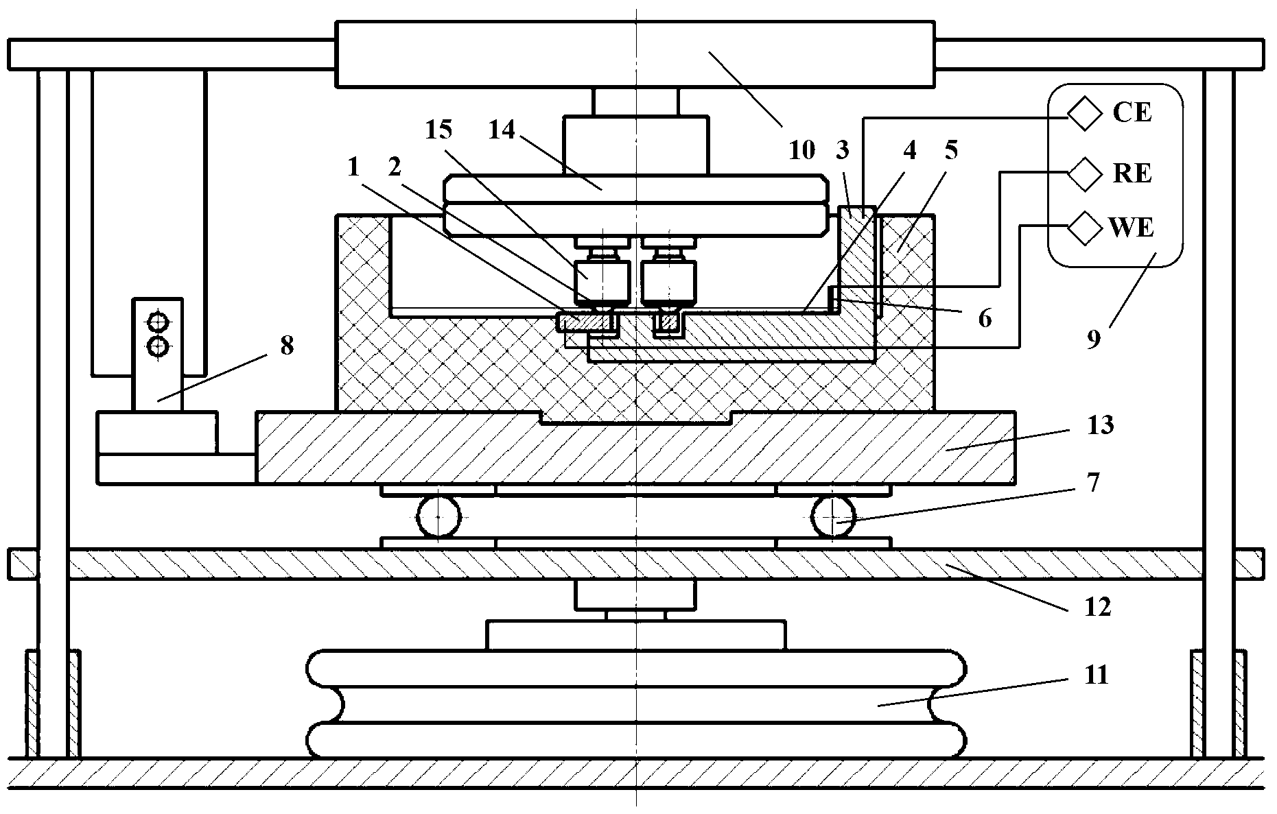
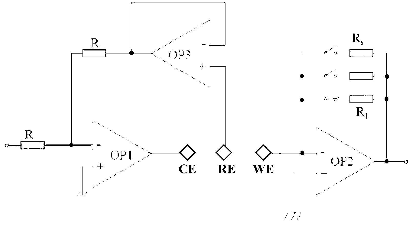
[0058] Such as figure 1 As shown, the device 1000 for implementing the method for controlling the friction coefficient between friction pairs of the present invention includes: a first friction member 1, a second friction member 2, a counter electrode 3, a lubricant 4, a lubrication pool 5, a reference electrode 6, Thrust ball bearing 7, force sensor 8, potentiostat 9, speed control system 10, loading device 11, lifting table 12, lubrication pool base 13, coupling 14 and clamp 15, of which 4 is lubricant, first friction The piece 1 and the second friction piece 2 form a friction pair.

[005...

Example Embodiment

[0065] Example 1

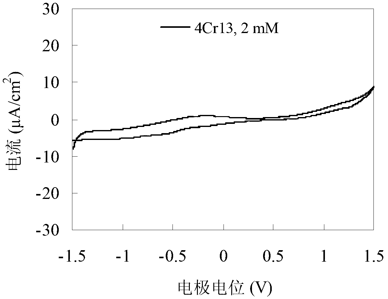
[0066] With reference to the above description of the specific embodiments of the method for controlling the friction coefficient between the friction pairs of the present invention, figure 1 The device shown is a platform that implements the method of controlling the friction coefficient between friction pairs of the present invention and detects the relationship between the friction coefficient and the electrode potential. Among them, such as figure 1 The first friction member 1 shown is a stainless steel (model 4Cr13) disc, the second friction member 2 is a zirconium dioxide ball (2 in total, with the same radius of gyration), and the lubricant 4 is sodium lauryl sulfate Propylene carbonate solution.

[0067] In this embodiment, the response result of the friction coefficient changing with the electrode potential is obtained, and the purpose of controlling the friction coefficient between the friction pairs is achieved. specifically, Figure 5 with Image 6 A...

Example Embodiment

[0069] Example 2

[0070] Similarly, referring to the foregoing description of the specific embodiments of the method for controlling the friction coefficient between the friction pairs of the present invention, figure 1 The device shown is a platform that implements the method of controlling the friction coefficient between friction pairs of the present invention and detects the relationship between the friction coefficient and the electrode potential. Among them, such as figure 1 The first friction member 1 shown is a stainless steel (model 4Cr13) disc, the second friction member 2 is a zirconium dioxide ball (3 in total, with the same radius of gyration), and the lubricant 4 is sodium lauryl sulfate Propylene carbonate solution.

[0071] Figure 7-9 A schematic diagram of the response curve of the friction coefficient with the electrode potential of this embodiment is shown. among them, Figure 7 The working conditions involved are: the normal load of the friction pair is 500N,...


PUM


Abstract

The invention discloses a lubricating agent, a friction pair and a method for controlling a friction coefficient between the friction pair. In the method for controlling the friction coefficient between the friction pair, the friction pair comprises a first friction piece and a second friction piece. The method comprises the following steps of: applying the lubricating agent between the first friction piece and the second friction piece; applying a potential to the first friction piece through the lubricating agent; and controlling the friction coefficient between the first friction piece and the second friction piece by controlling the potential, wherein the lubricating agent comprises propylene carbonate and an additive; and the additive is selected from at least one of a cationic surfactant, an anion surfactant and a zwitter-ion surfactant. The method is easy, convenient and practicable, and has a large applicable load speed range; and according to the method, the friction coefficient between the friction pair can be controlled effectively, and electrochemical corrosion of the friction pieces of the friction pair can be delayed effectively, even avoided.

Description

Technical field [0001] The present invention relates to the field of electromechanical technology. Specifically, the present invention particularly relates to a lubricant, a friction pair and a method for controlling the friction coefficient between the friction pair. Background technique [0002] Friction and wear are common phenomena in machine operation, and the friction characteristics are mainly affected by factors such as friction pair materials, lubrication status, speed, and load. In the long-term production practice, people's understanding of friction has been continuously improved, and various inventions that utilize or inhibit friction have emerged, such as belt transmission technology, rolling bearings, and so on. These technologies are all passively controlled friction technologies, and the friction characteristics of relevant friction components have been determined by specific design and manufacturing technologies before use. [0003] In applications such as frictio...

Claims


Application Information

Patent Timeline
IPC IPC(8): F16N15/00C10M169/04
CPCF16N15/00F16N2250/42F16N29/00C10M169/04C10M177/00C10M2207/126C10M2207/325C10M2219/042C10M2219/044C10N2010/02C10N2030/02C10N2030/60C10N2040/02G01N33/2888Y10T74/19991
Inventor 孟永钢阳小勇田煜
Owner TSINGHUA UNIV
Why Eureka
Try Eureka