Solid waste treatment equipment and application thereof in brick kiln

A technology for solid waste and treatment equipment, applied in the field of chemical machinery, can solve the problems of carbon machine pressure rise, plugging, space pollution, etc., and achieve the effect of improving processing speed, promoting high-temperature treatment, and preventing plugging phenomenon.

Active Publication Date: 2013-05-01
白志广
View PDF5 Cites 5 Cited by
  • Summary
  • Abstract
  • Description
  • Claims
  • Application Information

AI Technical Summary

Problems solved by technology

[0002] At present, the treatment of solid waste usually adopts burial, combustion or carbonization, among which burial will occupy a large space, resulting in a great waste of space, forming another kind of space pollution; while solid waste will be burned during the burning process. It produces more gas, and if the combustion temperature is low, it will also produce harmful gases such as dioxin that pose a huge threat to human health, and the environment is seriously polluted
In the current carbonization treatment, when solid waste is carbonized in the carbon machine, it usually occurs that the solid waste cannot be completely dried out, and it is directly carbonized. Water vapor will be generated during carbonization, and the water vapor cannot be effectively discharged, resulting in When the air pressure rises, the air pressure will block the carbonization of solid waste, resulting in the phenomenon of machine jam, the efficiency of solid waste treatment is greatly weakened, and the treatment effect is also forced to weaken

Method used


Image

  • Solid waste treatment equipment and application thereof in brick kiln
  • Solid waste treatment equipment and application thereof in brick kiln
  • Solid waste treatment equipment and application thereof in brick kiln

Examples


Embodiment Construction

[0038] The technical solutions of the various embodiments of the present invention will be clearly and completely described below in conjunction with the accompanying drawings. Apparently, the described embodiments are only some of the embodiments of the present invention, not all of them. Based on the embodiments of the present invention, all other embodiments obtained by persons of ordinary skill in the art without making creative efforts belong to the protection scope of the present invention.

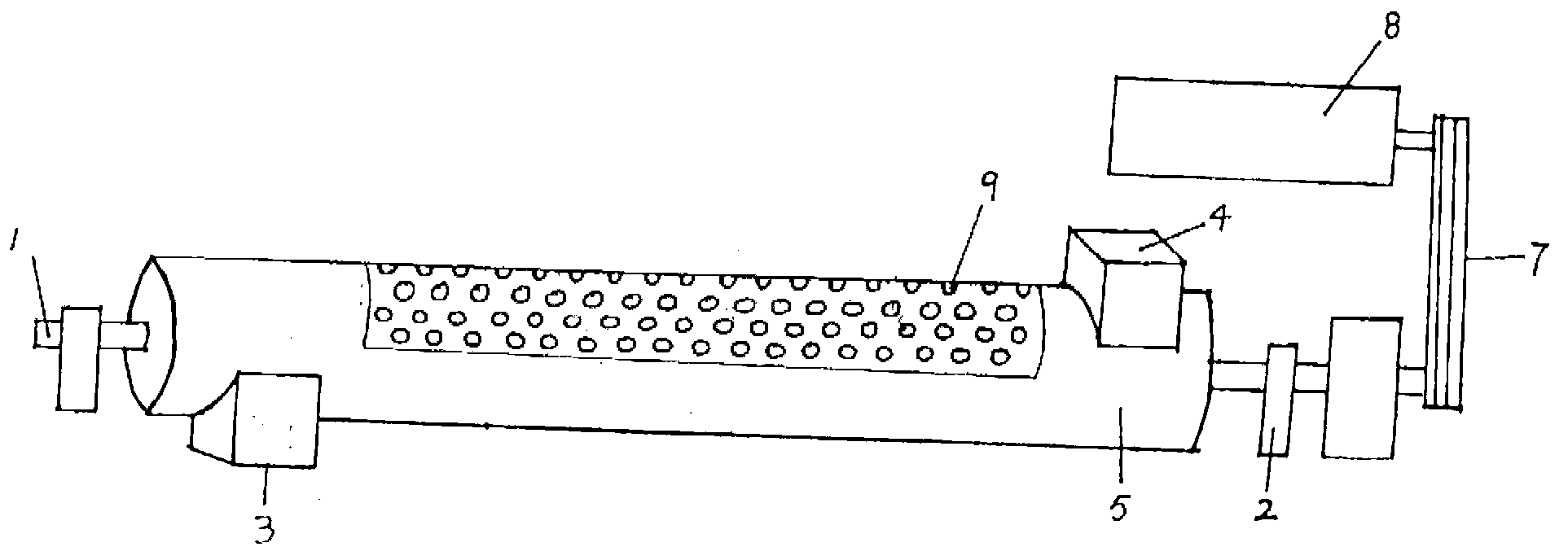
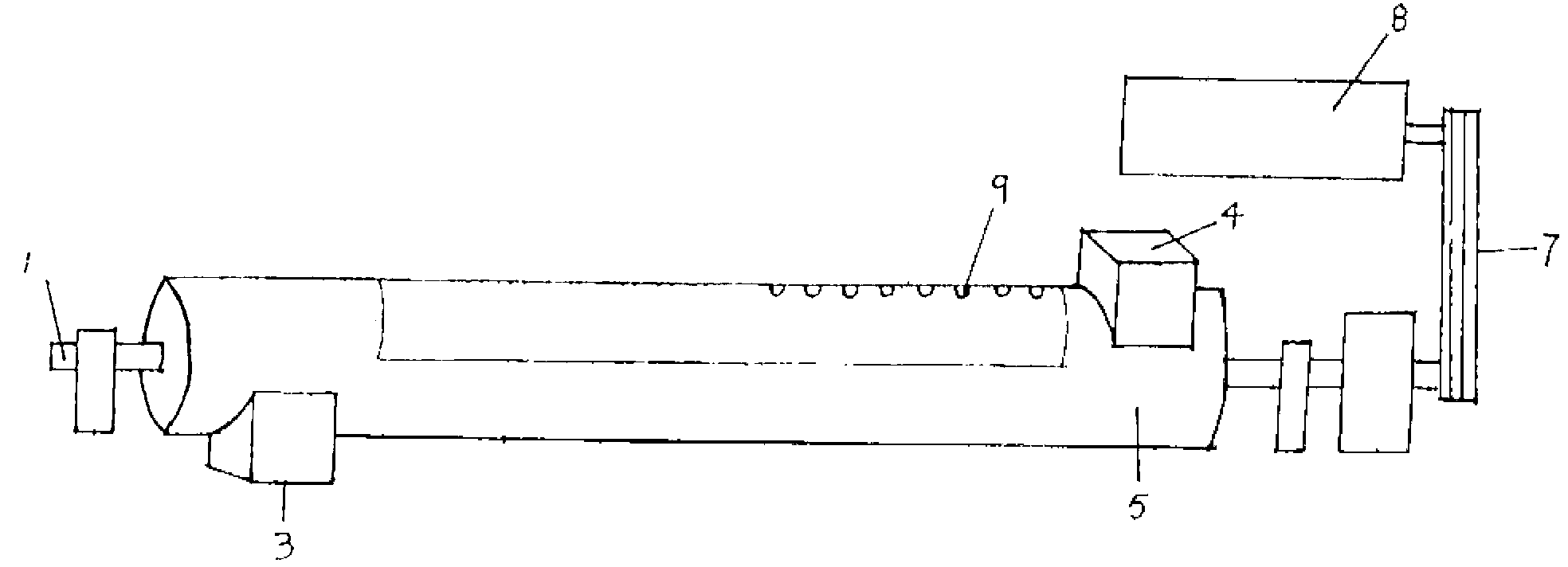
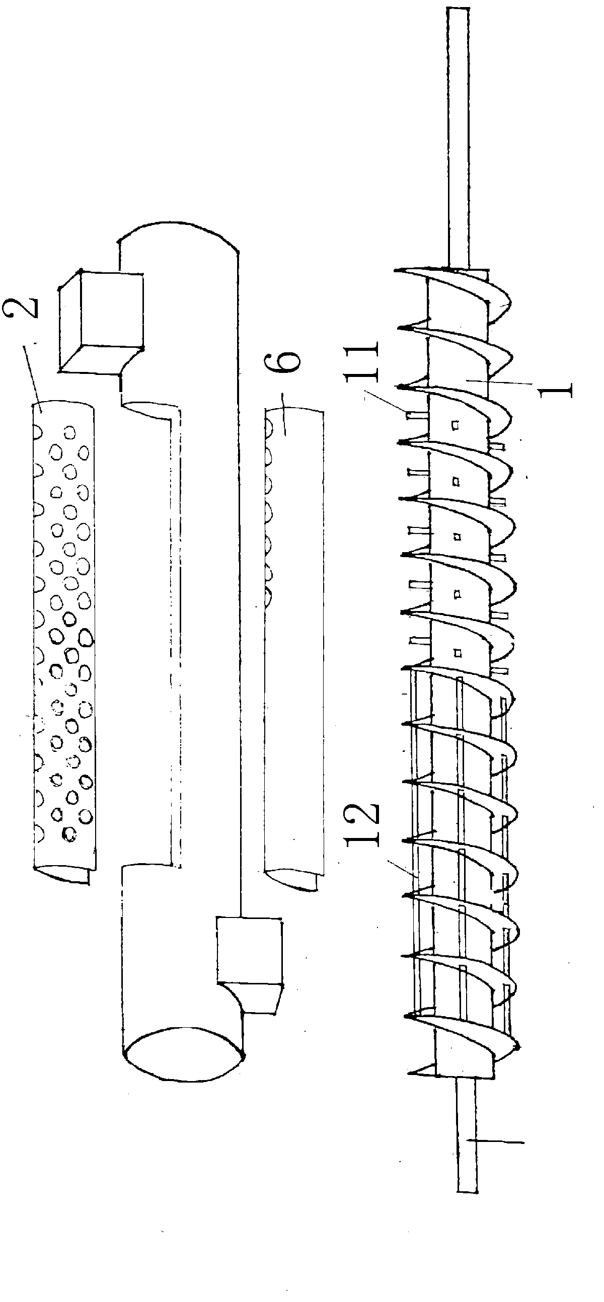
[0039] The invention provides a kind of solid waste processing equipment, which comprises a long cylindrical casing placed horizontally, one end of the long cylindrical casing is provided with an inlet, and the other end is provided with an outlet, along the axial direction of the long cylindrical casing A helical shaft is provided, and the helical shaft is provided with more than one longitudinal stirring rod perpendicular to the helical shaft on the side close to the inlet, and one...


PUM


Abstract

The invention relates to chemical machinery, in particular to solid waste treatment equipment and an application. The solid waste treatment equipment comprises a long barrel-shaped shell which is horizontally arranged, wherein an inlet is formed in one end of the long barrel-shaped shell, and an outlet is formed in the other end of the long barrel-shaped shell; a spiral rotating shaft is arranged along the axial direction of the long barrel-shaped shell, more than one longitudinal stirring rods which are perpendicular to the spiral rotating shaft are arranged on one side, which is near the inlet, of the spiral rotating shaft, and more than one transverse stirring rods which are parallel to the spiral rotating shaft are arranged on one side, which is near the outlet, of the spiral rotating shaft; and an upper shell which can be opened is arranged on the upper part of the long barrel-shaped shell, and more than one through holes are formed in the upper shell. The solid waste treatment equipment is put in a flat-top tunnel brick kiln, high temperature in the flat-top tunnel brick kiln is utilized to treat solid waste in the solid waste treatment equipment, the spiral rotating shaft is rotated, the solid waste is stirred by the longitudinal stirring rods, so as to evaporate moisture, and the solid waste is stirred by the transverse stirring rods, so as to loosen the solid waste. According to the solid waste treatment equipment, the treatment of the solid waste can be promoted, and gas can be effectively exported.

Description

technical field [0001] The invention relates to chemical machinery, in particular to solid waste treatment equipment and its use in brick kilns. Background technique [0002] At present, the treatment of solid waste usually adopts burial, combustion or carbonization, among which burial will occupy a large space, resulting in a great waste of space, forming another kind of space pollution; while solid waste will be burned during the burning process. More gas is produced, and if the combustion temperature is low, it will also produce harmful gases such as dioxins that pose a huge threat to human health, and the environment is seriously polluted. In the current carbonization treatment, when solid waste is carbonized in the carbon machine, it usually occurs that the solid waste cannot be completely dried out, and it is directly carbonized. Water vapor will be generated during carbonization, and the water vapor cannot be effectively discharged, resulting in When the air pressure...

Claims


Application Information

Patent Timeline
Patent Type & Authority Applications(China)
IPC IPC(8): F26B17/20F26B25/04F26B25/00F27D17/00
Inventor 白志广
Owner 白志广
Why Eureka
Try Eureka