Debugging system for motor

A debugging system and motor-driven technology, applied in control systems, control generators, vector control systems, etc., can solve problems such as difficulty in meeting the requirements of anti-interference and real-time performance, and achieve the effect of convenient fault diagnosis and convenient control

Inactive Publication Date: 2013-05-01
SOUTH CHINA UNIV OF TECH
View PDF5 Cites 3 Cited by
  • Summary
  • Abstract
  • Description
  • Claims
  • Application Information

AI Technical Summary

Problems solved by technology

[0004] (1) It can only meet the needs of specific users, such as Starter and Drivemonitor, the on-site debugging tools for transmission equipment developed by Siemens, can only be used in specific occasions;
[0005] (2) RS232, RS485, USB and other communication methods are mostly used, and motors are mostl

Method used


Image

  • Debugging system for motor
  • Debugging system for motor
  • Debugging system for motor

Examples


Embodiment

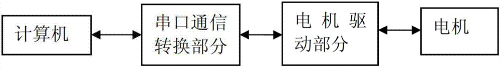
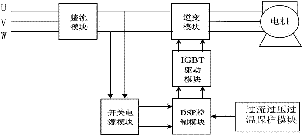
[0029] Such as figure 1 As shown, the motor debugging system of the present invention includes a computer (LabVIEW software is installed), a motor drive part and a serial port communication conversion part, such as figure 2 As shown, the motor drive part includes a DSP control module, a rectification module, an IGBT drive module, an inverter module, a switching power supply module, and an overcurrent, overvoltage, and overtemperature protection module. The rectification module is connected to the motor through an inverter module. The rectifier module is connected to the DSP control module through the switching power supply module; the IGBT drive module is connected to the inverter module and the DSP control module respectively, and the overcurrent, overvoltage and overtemperature protection module is connected to the DSP control module.

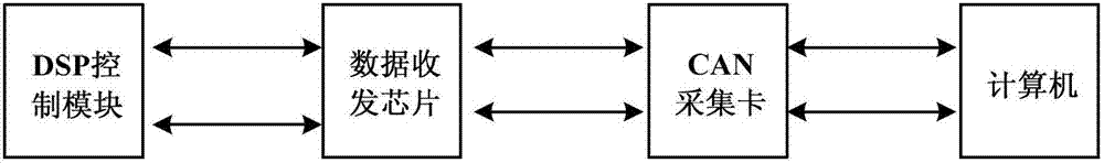
[0030] Such as image 3 As shown, the data transceiver chip (using PCA82C250) and the CAN acquisition card (using USBCAN-II) included in t...


PUM


Abstract

The invention discloses a debugging system for a motor. The debugging system comprises a computer, a motor driving part and a serial port communication converting part, wherein the motor driving part comprises a DSP (Digital signal Processor) control module, a rectifier module, an IGBT (Insulated Gate Bipolar Transistor) inverter module, a switch power supply module, a driving module and an over-current, over-voltage and over-temperature protecting module. The debugging system disclosed by the invention can be used for acquiring actual voltage signals, current signals, rotating speed signals and the like and acquiring an internal control variable.

Description

technical field [0001] The invention relates to the field of motor control, in particular to a motor debugging system. Background technique [0002] The traditional motor debugging system mainly uses traditional test instruments to collect data such as voltage, current, power, speed, and torque. Through manual reading, data recording, and curve drawing, the measurement and control speed is slow, the data is inaccurate, and the data processing and analysis are complicated. , and it is especially difficult to measure multiple signals at the same time for graphical comparison. [0003] Many motor debugging platforms developed at present have the following problems: [0004] (1) It can only meet the needs of specific users, such as Starter and Drivemonitor, the on-site debugging tools for transmission equipment developed by Siemens, can only be used in specific occasions; [0005] (2) RS232, RS485, USB and other communication methods are mostly used, and motors are mostly used...

Claims


Application Information

Patent Timeline
IPC IPC(8): H02P21/00
Inventor 游林儒文小琴黄招彬李继平
Owner SOUTH CHINA UNIV OF TECH
Why Eureka
Try Eureka