
Process for production of adhesive optical film

一种光学薄膜、制造方法的技术,应用在表面预处理的粘合方法、粘合剂类型、化学仪器和方法等方向,能够解决光学特性影响、无法满足高耐久性、光学薄膜溶剂龟裂等问题,达到提高密合性、提高涂布外观性、防止溶剂龟裂的效果

Active Publication Date: 2013-05-01
NITTO DENKO CORP
View PDF17 Cites 7 Cited by
  • Summary
  • Abstract
  • Description
  • Claims
  • Application Information

AI Technical Summary

Problems solved by technology

This affects the optical properties, and may not be able to satisfy high durability in high heat and high humidity environments
[0009] As described above, in the prior art, there is no example focusing on the problem of solvent cracking on the side of the anchor layer forming surface of the optical film, and further research is required to improve the problem.

Method used


Image

  • Process for production of adhesive optical film
  • Process for production of adhesive optical film
  • Process for production of adhesive optical film

Examples


Embodiment 1

[0132] (Production of optical films (polarizers))

[0133] A polyvinyl alcohol film with a thickness of 80 μm was dyed in a 0.3% iodine solution at 30° C. for 1 minute between rollers with different speed ratios, and stretched to 3 times. Then, it was immersed in an aqueous solution containing 60°C, 4% boric acid, and 10% potassium iodide for 0.5 minutes, and stretched to a total stretching ratio of 6 times. Next, after immersing in an aqueous solution containing 1.5% potassium iodide at 30° C. for 10 seconds to wash, and then drying at 50° C. for 4 minutes, a polarizing plate was obtained. A cellulose triacetate film (trade name "KC4UY", manufactured by Konica Minolta Holdings, Inc.) with a thickness of 40 μm was bonded to the viewing side of the polarizer with a polyvinyl alcohol-based adhesive, and on the side where the adhesive was applied A retardation plate made of a norbornene-based resin film with a thickness of 33 μm (trade name “ZEONOR FILM ZD12”, manufactured by ZE...

Embodiment 2~21 and 23~27

[0142] Embodiment 2~21 and 23~27, comparative example 1~5 and 7~15

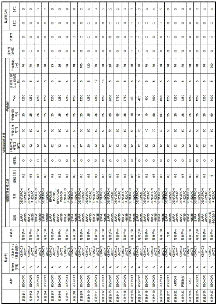
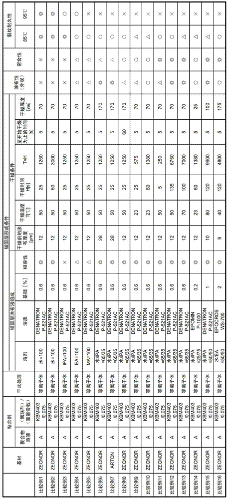
[0143] In the optical film (polarizing plate), the retardation film shown in Table 2 and Table 3 was used instead of the retardation film (ZEONOR FILM ZD12) on the side where the anchor layer was formed. type optical film.

Embodiment 22 and comparative example 7

[0145] On the retardation plate (acrylic resin film) side of the acrylic polarizing plate used in Example 23, an adhesive layer (20 μm) obtained using the above-mentioned adhesive solution was formed, and then, as an adhesive retardation plate “ARTON ”; an optical film (substrate) (manufactured by JSR Corporation) made of a cyclic polyolefin resin (norbornene-based resin) is further laminated, and an anchor layer is formed on the side of the phase difference plate (ARTON). A pressure-sensitive adhesive optical film was produced in the same manner as in Example 1.

[0146] In Table 2 and Table 3, "substrate" indicates the retardation plate on the side where the anchor layer is formed, and "dry treatment" indicates the type of treatment performed on the side where the anchor layer is formed of the base material, and

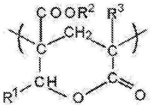
[0147] "Acrylic" means an optical film formed from a lactone-modified acrylic resin,

[0148] "TAC" means an optical film formed of saponified cellulose triacetat...


PUM

PropertyMeasurementUnit
glass transition temperatureaaaaaaaaaa
particle diameteraaaaaaaaaa

Abstract

A process for producing an adhesive optical film, comprising a step of applying an anchor layer coating solution that comprises a mixed solvent containing water and an alcohol as the main components and a binder resin onto an optical film in such a manner that the thickness of the resulting coating before drying becomes 20 [mu]m or less and then drying the resulting product under the drying conditions which fulfill both the requirements (1)-(2) mentioned below to remove the mixed solvent, thereby forming an anchor layer: (1) the drying temperature (T) is 40 to 70 DEG C; and (2) a value (TH) produced by multiplying the drying temperature (T) ( DEG C) with a drying time (H) (sec) is 400 to 4000 inclusive.

Description

technical field [0001] The present invention relates to a method for producing an adhesive optical film in which an adhesive layer is laminated on at least one side of the optical film via an anchor layer. Examples of the optical film include surface treatment films such as polarizing plates, retardation films, optical compensation films, brightness enhancement films, and antireflection films, and films obtained by laminating them. Background technique [0002] In liquid crystal display devices, organic EL display devices, etc., due to the image forming method, for example, in liquid crystal display devices, polarizing elements must be arranged on both sides of the liquid crystal cell, and polarizing plates are usually attached. Furthermore, in display panels such as liquid crystal panels and organic EL panels, in addition to polarizing plates, various optical elements have begun to be used in order to improve the display quality of the display. In addition, front panels ar...

Claims


Application Information

Patent Timeline
Patent Type & Authority Applications(China)
IPC IPC(8): C09J7/02B05D3/02B32B27/00C09D5/00C09J201/00C09J7/50
CPCC09J133/08C09D7/001C09J2465/003B05D5/10B32B27/00C09J5/02C09J2433/003C09J2465/006B32B27/30G02B5/30C09J2433/006C09J7/0257C09J7/02C09J11/06C09D7/20C09J7/50C09J7/22C09J7/38B05D3/0254C08J5/18G02B5/3025G02B5/305C09J2301/40C09J2301/312C09J2301/416
Inventor 外山雄祐保井淳木村智之佐竹正之
Owner NITTO DENKO CORP
Learn More