Flat edge-trimming machine

A technology of edge trimmer and flat mouth, which is applied in metal processing and other directions, can solve the problems of low operating efficiency of the whole machine, low power transmission efficiency, and inconspicuous guiding effect, and achieve low production accuracy requirements, low production cost, Fix easy effects

Inactive Publication Date: 2013-05-08
黄开强 +1
View PDF6 Cites 19 Cited by
  • Summary
  • Abstract
  • Description
  • Claims
  • Application Information

AI Technical Summary

Problems solved by technology

At present, for the process of edge trimming and trimming, most of the methods use an inner mold and an outer mold to trim the edge four times on the punch press according to four directions. The problem of this edge trimming is that the process is complicated and the work efficiency Low, the mold is easy to damage, especially when the height of the remaining material on the edge is inconsistent, or the products with stretched parts such as arcs, the trimming process is more complicated, and the mold manufacturing cost is higher. Therefore, people are trying to modify the mold. Trying to create a safe and easy way to cut edges
The flat edge trimming machine with the above structure can solve the problem of inefficiency in the edge trimming process of metal stretched parts to a certain extent. shaft, and then through an auxiliary shaft, the power is transmitted to the drive shaft. Multiple sprocket drives make the power transmission efficiency low, resulting in low operating efficiency of the whole machine
At the same time, after the structure completes a working cycle, only the automatic guiding parts are used to assist the spring pin, the spring block, and the spring sleeve to guide the origin of the fixed mold, and the guiding effect is not obvious, which also makes the operating efficiency of the whole machine lower.

Method used


Image

  • Flat edge-trimming machine
  • Flat edge-trimming machine
  • Flat edge-trimming machine

Examples


Embodiment approach

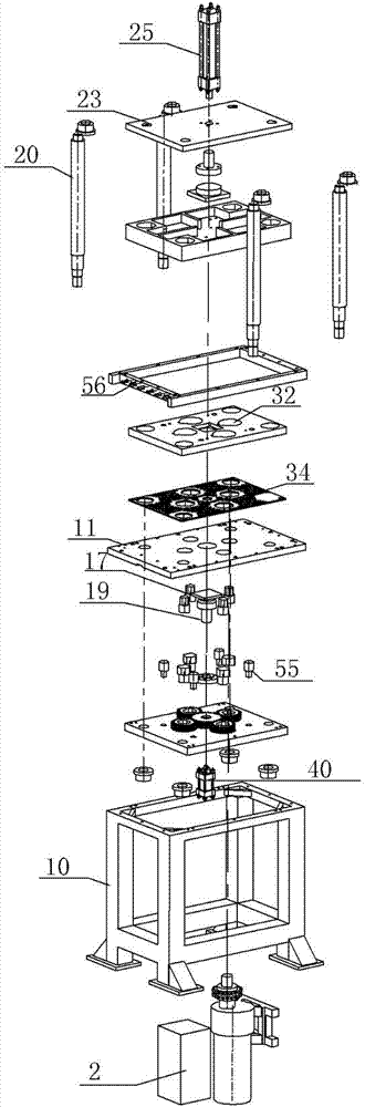
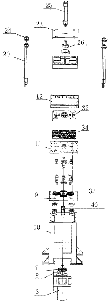
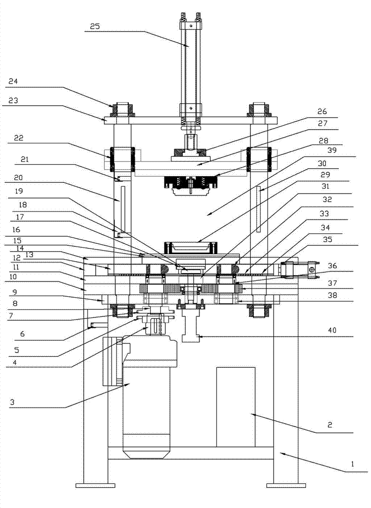
[0031] see Figure 1-3 , a flat edge trimming machine, mainly comprising: a frame 1, an electrical control box 2 placed in the frame 1 and a brake motor 3, an oil cylinder or an air cylinder device installed on the top of the frame 1, and a mold divided into upper and lower parts Assembly 39, which transmits the power of the brake motor 3 to the transmission part of the lower part of the mold assembly 39; the main shaft 8 in the transmission part is directly connected with the brake motor shaft 4 on the brake motor 3 through a sprocket; the brake motor The power of 3 is transmitted to the main shaft 8 after the brake motor shaft single row sprocket 5 on the brake motor shaft 4 engages with the main shaft single row sprocket 7 on the main shaft 8 . As another embodiment of the present invention, the brake motor shaft 4 of the brake motor 3 can be directly nested in the main shaft 8 in the transmission part, such as Figure 4 As shown, the brake motor 3 is an automatic brake...


PUM


Abstract

The invention relates to equipment for machining metallic sheet metal pieces, in particular to a flat edge-trimming machine. The flat edge-trimming machine mainly comprises a frame (1), an electrical appliance control box (2) and a braking motor (3) which are arranged in the frame (1), an oil cylinder or cylinder device which is arranged on the upper part of the frame (1), a die assembly (39) which is divided into upper and lower parts, a transmission component which transmits the power of the braking motor (3) to the lower part of the die assembly (39), and a guide oil cylinder or cylinder (35) which ensures that the lower part of the die assembly resets, wherein the transmission component comprises a spindle (8); and the spindle (8) in the transmission component is directly connected with a braking motor shaft (4) on the braking motor (3) through a chain wheel, and the power of the braking motor (3) is transmitted to the spindle (8) after a braking motor shaft single-row chain wheel (5) on the braking motor shaft (4) is engaged with a spindle single-row chain wheel (7) on the spindle (8). The invention is characterized in that the flat edge-trimming machine can trim regularly, is low in cost, and is safe and reliable; and the flat edge-trimming machine can easily remove excess materials on the edges of drawn pieces, so that the processes are simplified, the labor intensity of workers and the machining time are reduced, the production efficiency is improved, and accident work injuries can be avoided.

Description

Technical field [0001] The present invention involves a metal sheet metal parts processing equipment, and specially involves a metal edge machine. Background technique [0002] For the shell or lid products that are stressed, stamped, stretching, and forming, generally stretch it, whether it is metal, plastic, or other materials.Cut the edges with the remaining parts.At present, most of the methods for cutting edges and trimming are used in an internal mold and an outer mold in four directions to cut the edge in four directions.Low, molds are easily damaged, especially when the marginal remaining materials are inconsistent, or stretching parts such as arcs are more complicated and the mold production costs are more complicated. Therefore, people are trying to transform molds.Try to create a safe, simple cut -edge method. [0003] An existing technology flat -cutting machine, including: racks, electrical control boxes set in the rack, and power devices that are connected to it and...

Claims


Application Information

Patent Timeline
Patent Type & Authority Applications(China)
IPC IPC(8): B21D28/02B21D28/14B21D28/20B26F1/38B26F1/44B26D5/18
Inventor 黄开强
Owner 黄开强
Why Eureka
Try Eureka