Deflection-resisting rail spacing device

A fixed-distance and yaw technology, applied in the field of rail transit, can solve the problems of anti-rail wear performance, inability to control the deflection and vibration of the rail, and inability to limit the vibration displacement of the rail head.

Active Publication Date: 2013-05-08
QINGDAO CREATE ENVIRONMENT CONTROL TECH +1
View PDF7 Cites 7 Cited by
  • Summary
  • Abstract
  • Description
  • Claims
  • Application Information

AI Technical Summary

Problems solved by technology

However, because the rail has a certain height, the lateral force generated by the wheel-rail interaction acts on the rail head of the rail, which will generate a large bending distance relative to the rail bottom, and the existing fixed-distance connecting rod is basically designed for tensile strength. The bending moment is less considered, so the existing fixed-distance connecting rod is strong in tension and weak in bending. Therefore, this fixed-distance connecting rod can ensure the gauge of the rail bottom, but cannot limit the vibration displacement of the rail head due to the bending moment
Therefore, the rail will still vibrate, and the wear and corrugation of the rail cannot be suppressed.
[0004] To sum up, the existing technology cannot cope with the bending distance generated at the rail head relative to the rail bottom when the rail is working, so the deflection and shimmy phenomenon of the rail cannot be controlled, so the performance of preventing rail wear is greatly affected , the market urgently needs a new product that can completely solve the above problems
[0005] In addition, the application of highly elastic fasteners causes large vertical and lateral displacements and noises on the rails, which affects the comfort of the train. In order to reduce the vibration amplitude of the rails without changing the elasticity of the fasteners, it is best The best way is to increase the para-vibration mass of the rail fastener vibration isolation system, but most of the fastener systems so far do not have much space and mounting parts for increasing the mass

Method used


Image

  • Deflection-resisting rail spacing device
  • Deflection-resisting rail spacing device
  • Deflection-resisting rail spacing device

Examples


Embodiment 1

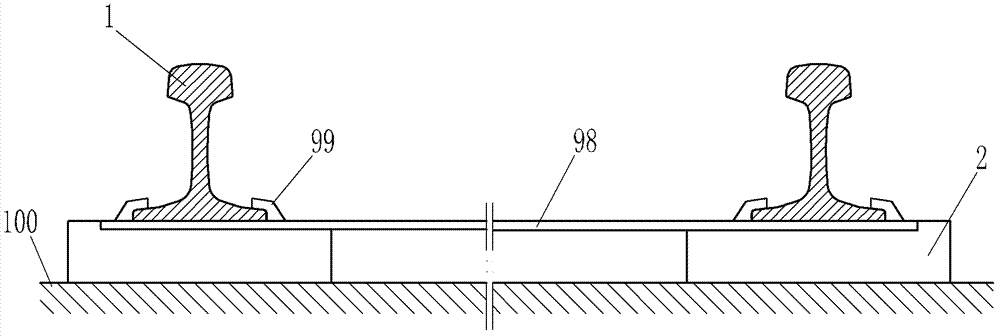
[0071] like figure 1 As shown, taking the short sleeper ballastless track bed as an example, the short sleeper 2 is fixed on the track bed 100 , and the steel rail 1 is erected above the short sleeper 2 . The existing fixed-distance connecting rod includes a connecting rod 98 disposed between two parallel steel rails 1 , and two ends of the connecting rod 98 are provided with bayonet openings 99 , which are locked and fixed at the rail bottoms of the two steel rails 1 respectively. The connecting rod 98 in the existing fixed-distance connecting rod is basically designed for tensile strength, and less consideration is given to the bending moment, so the existing fixed-distance connecting rod has strong tensile strength and weak bending resistance, so this fixed-distance connecting rod can ensure the rail. The rail gauge at the bottom can not limit the vibration displacement of the rail head due to the bending moment. Since the bayonet of this spacer bracket is locked at the bo...

Embodiment 2

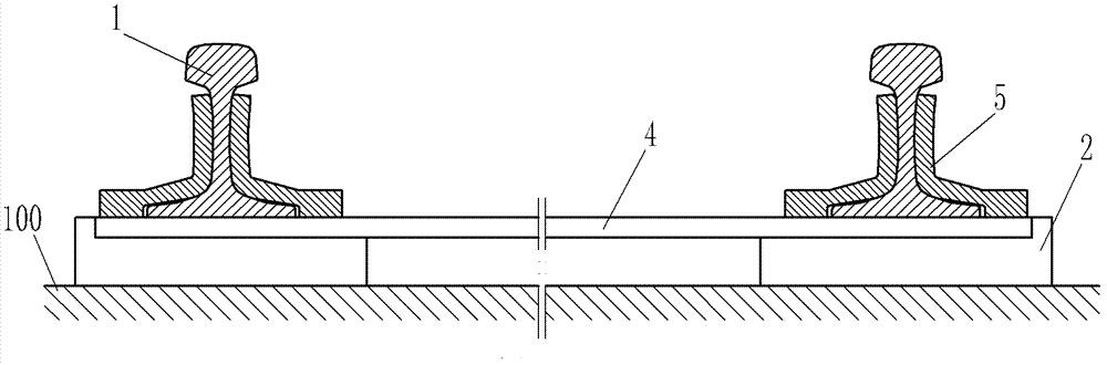
[0080] like Figure 5 The difference between the track anti-yaw and distance device of the present invention and the first embodiment is that the anti-bending coupling beam 4 is made of FRP material, and the anti-swing splint 5 is fixed on the anti-bending coupling beam 4 by means of fasteners 8 .

[0081] Since the detachable structure is adopted between the anti-swing splint 5 and the anti-bending coupling beam 4, the assembly, maintenance and replacement are more convenient, and the installation of the track anti-sway and distance device of the present invention can be completed without disassembling the rail. Or replacement, suitable for existing line reconstruction or new line laying, especially suitable for use on seamless steel rails that are currently widely used.

Embodiment 3

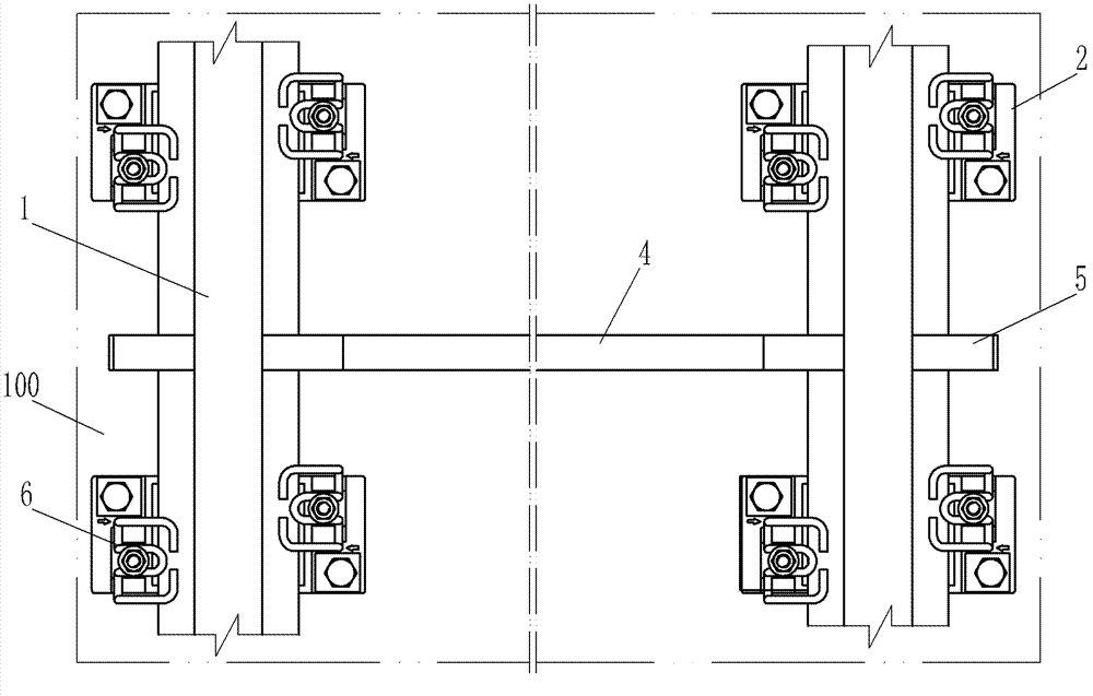
[0083] like Image 6 The difference between the track anti-yaw and spacer device of the present invention and the second embodiment is that the track anti-yaw and spacer device of the present invention can also be used for short sleeper ballast bed, normally laying ballast 9 on the track bed 100 is Can. Furthermore, using Image 6 The shown anti-swing splint 5 has a higher clamping force point for the rail waist, and has a stronger ability to bear the force distance of the rail head, so the performance of resisting the deflection of the rail is better. In addition, in order to reduce the assembly process and improve the installation efficiency, the two anti-swing splints 5 in the same direction in the clamping assembly are welded and fixed on the anti-bending coupling beam 4, and the other two anti-swing splints 5 in the same direction are fixed by the fasteners 8 on the flexural coupling beam 4. The anti-bending coupling beam 4 is made of square steel rods.

[0084] When ...


PUM


Abstract

The invention relates to a rail accessory, in particular to a deflection-resisting rail spacing device which comprises anti-bending binding beams and clamping components. The anti-bending binding beams are located below two steel rails on the same line and located between each two adjacent fasteners in the longitudinal direction of the steel rails, and the clamping components clamp and fix the two steel rails at steel rail webs or rail bottoms and at least partially fixed on the anti-bending binding beams. Transverse stiffness of the steel rails is enhanced while bending moment generated by the opposite rail bottoms when outside disturbing force is acted on rail heads of the steel rail can be offset effectively, shimmy of the steel rails during working can be controlled effectively, and the deflection-resisting rail spacing device is outstanding in advantage of overquick wear prevention of the steel rails and obvious in effect. In addition, the deflection-resisting rail spacing device is capable of effectively improving comfortability during train running and achieving excellent noise reduction performance, has the advantages of simple and compact structure, high utilization rate of rail space, excellent vibration reduction and noise reduction performances, economy, practicality, high applicability and the like, and quite wide in market application prospect.

Description

technical field [0001] The invention belongs to the field of rail traffic, and relates to a rail accessory, in particular to a distance-fixing device that can limit the distance between steel rails and can limit the deflection and vibration of the steel rails. Background technique [0002] In recent years, under the development trend of the continuous high-speed rail transit, the requirements for vibration reduction and noise reduction of rail transit are increasing day by day. In order to solve the problem of vibration and noise disturbing the public during the operation of rail transit, various high-elasticity pads and high-elasticity fasteners have been widely used. The application of these vibration reduction measures significantly reduces the vertical stiffness of the rail, and achieves a good vibration reduction effect. However, since the lateral stiffness of the rail is also reduced, the lateral vibration of the rail increases, resulting in the wheel rail when the veh...

Claims


Application Information

Patent Timeline
Patent Type & Authority Applications(China)
IPC IPC(8): E01B19/00E01B9/60E01B9/62E01B9/68
Inventor 尹学军雷晓燕孔祥斐曾向荣刘伟宁任静
Owner QINGDAO CREATE ENVIRONMENT CONTROL TECH
Why Eureka
Try Eureka