Wave-activated generator

A generator and wave technology, applied in ocean energy power generation, engine components, machines/engines, etc., can solve the problems of insufficient support, high cost, weak power generation capacity, etc., and achieve a simple structure, low cost, and strong power generation capacity. Effect

Inactive Publication Date: 2013-05-08
李念君
View PDF6 Cites 4 Cited by
  • Summary
  • Abstract
  • Description
  • Claims
  • Application Information

AI Technical Summary

Problems solved by technology

But at present, most of these power devices have complex structures and high costs. There are also some power devices, such as power devices that use thermal power to generate electricity. These energy sources are non-renewable and will cause environmental pollution to varying degrees.
[0003] The invention of Chinese patent No. 200410060714.8 discloses a kinetic potential energy generating power device, which includes an output main shaft and a frame that output power to the generator, and is arranged on a carrier that can generate irregular motion together with the generator, and is characterized in that It includes: a one-way transmission mechanism that inputs power from the balance shaft; a wind-up energy storage and uniform energy release device that obtains power from the one-way mechanism, and the device transmits the stored energy to the output in the form of smooth rotation The main shaft, this invention is matched with the generator and installed on the moving car, boat and sea surface, or can drive the output main shaft to rotate irregularly up and down, front and back, left and right, so that the rotating output main shaft can drive the generator rotor to rotate, so as to drive the power generation The purpose of this power plant is to convert kinetic potential energy into electric energy without consuming energy and polluting the environment. However, this invention has the defect of weak power generation capacity due to insufficient support force of the pendulum shaft.

Method used


Image

  • Wave-activated generator
  • Wave-activated generator

Examples


Embodiment Construction

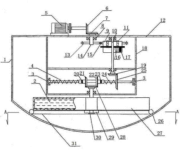
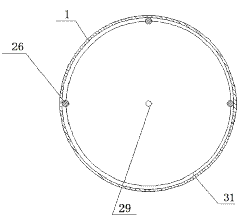
[0015] exist figure 1 As can be seen in the schematic diagram of the front view of the structure, the present invention includes a kinetic potential energy generator power device, and a kinetic potential energy generator power device includes an output main shaft 14 and an input gear 13 thereof, a frame 18, a pendulum weight 27 and a pendulum shaft 30 thereof, and is formed by a lower umbrella Gear 28, left bevel gear 21, left one-way movable gear sleeve 23, left spring 4, right bevel gear 22, right one-way movable gear sleeve 23, right spring 24, driven bevel gear 19, driving bevel gear 25 and transverse shaft The one-way transmission mechanism that 3 constitutes; Winding spring energy storage and all can release device that are made of winding shaft 10, output gear 15, ratchet one-way device 9, ratchet box 11, barrel 17 and clockwork spring 16. Wherein, the pendulum 27 is a closed semicircular shell, combined with figure 2 It can be seen that the pendulum weight is a semic...


PUM


Abstract

The invention discloses a wave-activated generator. The wave-activated generator is characterized in that water is injected in a swing lead, and flexibility of the swing lead is enhanced by utilizing the characteristic that water flows downwards; the swing lead can move left and right or in a circular mode when any angle high-low difference generates under the effect of waves; by a one-way transmission mechanism on a transverse shaft, and the purpose that energy is input into an energy accumulation spring in a one-way mode no mater which motion the swing lead carries out is achieved; the problem of energy interruption when the swing lead carries out different types of motion can be solved through an energy accumulation and uniform energy release device which can accumulate energy and input the energy to the generator continuously at constant speed; and the problem of insufficient swing shaft supporting force can be solved through a swing lead bearing wheel, and therefore generating capacity can be enhanced to the maximum. The wave-activated generator adopts wave energy which is a kind of energy in endless supply such as water energy, wind energy and solar energy. How to develop and utilize the wave energy is an international significant task, and the wave-activated generator just focuses on the task.

Description

technical field [0001] The invention relates to a generator set, in particular to a wave generator. Background technique [0002] Electric energy is widely used in people's life and production activities, and is the main driving force for scientific development and economic progress. The way people obtain electric energy now is mainly from the conversion of natural forms of energy, such as water energy, heat energy and wind energy, etc., through which energy is converted into a power plant to do work, thereby driving the rotor of the generator to rotate and generate electric energy. But at present, most of these power devices have complex structures and high costs, and some power devices, such as power devices that use thermal power to generate electricity, are non-renewable and cause environmental pollution to varying degrees. [0003] The invention of Chinese patent No. 200410060714.8 discloses a kinetic potential energy generating power device, which includes an output m...

Claims


Application Information

Patent Timeline
Patent Type & Authority Applications(China)
IPC IPC(8): F03B13/14
CPCY02E10/38Y02E10/30
Inventor 李念君李沛
Owner 李念君
Why Eureka
Try Eureka