Two-way plug-in mounting vibrating valve and electric hydraulic control unit

A technology of cartridge valve and vibration valve, which is applied in fluid pressure actuators, servo motor components, mechanical equipment, etc., can solve the problems that affect the quality of road roller operation, and the operator's work comfort and insurmountable problems, so as to shorten the vibration stop time , Reduce pressure loss, improve the effect of oil flow capacity

Active Publication Date: 2013-05-08
PERMCOTIANJINHYDRAULIC INC
View PDF6 Cites 15 Cited by
  • Summary
  • Abstract
  • Description
  • Claims
  • Application Information

AI Technical Summary

Problems solved by technology

[0003] Therefore, the technical problem to be solved by the present invention is that the vibrating valve block in the prior art cannot overcome the rotational inertia of the exciter rotor of the road roller, so that the vibration stop time is too long to cause the whole machine to resonate, which affects the operation quality of the road roller and the work of the operator. To solve the problem of comfort, provide a two-way plug-in vibration valve and an electro-hydraulic control unit that can effectively shorten the time for the hydraulic motor to stop, that is, the time for the roller to stop vibrating

Method used


Image

  • Two-way plug-in mounting vibrating valve and electric hydraulic control unit
  • Two-way plug-in mounting vibrating valve and electric hydraulic control unit
  • Two-way plug-in mounting vibrating valve and electric hydraulic control unit

Examples


Embodiment Construction

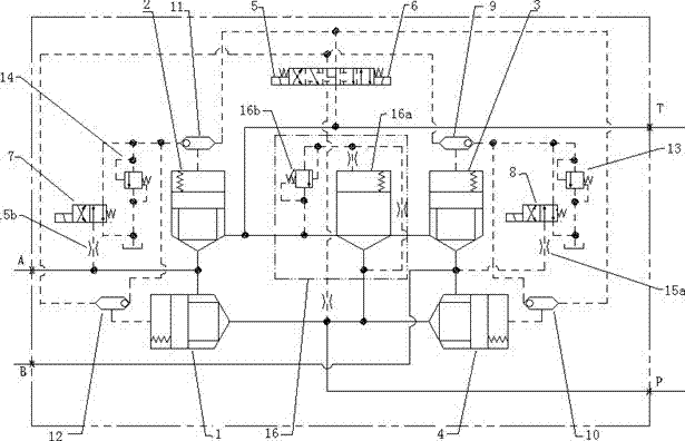
[0023] like figure 1 As shown, a two-way plug-in vibration valve in this embodiment includes

[0024]The valve body is formed with a plug-in cavity, an oil inlet port (P) connected to the oil outlet of the hydraulic pump, and an oil return port (T) connected to the oil return tank of the hydraulic system, respectively connected to the hydraulic motor The first working port (A) connected to the first oil port and the second oil port at both ends, and the second working port (B);

[0025] The main circuit, the main circuit is inserted in the insertion cavity of the valve body, including a direction control circuit composed of four two-way cartridge valves and a three-position four-way electromagnetic reversing valve, wherein

[0026] The first two-way cartridge valve 1 is arranged between the oil inlet port (P) and the first working port (A) to control the flow of the oil inlet port (P) to the first working port (A) For liquid supply, the third two-way cartridge valve ...


PUM


Abstract

The invention relates to a two-way plug-in mounting vibrating valve comprising a valve body and an electric hydraulic control loop. The valve body is plugged in a plug-in cavity of the valve body. The electric hydraulic control loop is used for controlling the operation of a hydraulic motor, and comprises a two-way plug-in valve, a control cover plate, a guide solenoid directional valve, an overflow valve and the like. The electric hydraulic control loop includes a directional auxiliary loop for controlling corotation and reversion of the hydraulic motor, an auxiliary loop for controlling stalling of the corotation and the reversion of the hydraulic motor, and another auxiliary loop for providing overload protection to the hydraulic vibration system of a pavement roller. The invention further relates to an electric hydraulic control unit comprising an exclusive-used vibrating controller for controlling the two-way plug-in mounting vibrating valve. By the aid of the vibrating controller, the operation time sequence of each solenoid valve can be controlled. By the invention, the hydraulic shock can be alleviated when a pavement roller starts oscillation, amplitudes and stops oscillation, peek value transmission of the hydraulic system can be reduced, and reliability and durability of the operation of the hydraulic components can be improved. The oscillation stop time is shortened and can be regulated and controlled, so that the working quality of the pavement roller is improved and the comfortableness of the drives is increased.

Description

technical field [0001] The invention relates to a two-way plug-in vibrating valve, in particular, a two-way plug-in vibrating valve for controlling the operation of a hydraulic motor on a vibratory road roller, and an electro-hydraulic valve with the two-way plug-in vibrating valve. control unit. Background technique [0002] In order to reduce the cost, the vibrating device of the domestic vibratory roller adopts the open hydraulic transmission and control system with constant pump (mostly gear pump) as the power source, which is relatively common. During the vibration start and stop process of the vibratory roller, the vibration frequency and vibration acceleration of the vibratory wheel have a change process from small to large or from large to small. During this short transition process, the vibration parameters of the vibratory wheel It is different from its vibration characteristics when it works in a steady state. In addition, the vibrating hydraulic motor starts wit...

Claims


Application Information

Patent Timeline
Patent Type & Authority Applications(China)
IPC IPC(8): F15B13/02
Inventor 郭熛王育春邰小琴戴明翰马兰
Owner PERMCOTIANJINHYDRAULIC INC
Why Eureka
Try Eureka