System used for conducting on-line monitoring for pushed slab kiln inner wall surface condition

A technology of pushing plate kiln and inner wall surface, which is applied in the direction of using optical devices, material analysis by optical means, measuring devices, etc., can solve the problems of lack of effective image analysis and processing methods, limitations of detection imaging, and inability to effectively perform detection and other problems , to achieve the effect of facilitating quality control and adjustment, improving detection accuracy and work efficiency, and improving detection efficiency and accuracy

Active Publication Date: 2013-05-08
WUHAN JOHO TECH
View PDF7 Cites 3 Cited by
  • Summary
  • Abstract
  • Description
  • Claims
  • Application Information

AI Technical Summary

Problems solved by technology

However, many test practices have shown that, first of all, for pusher kilns with operating temperatures as high as thousands of degrees Celsius, ordinary lasers often cannot effectively penetrate this high-temperature and high-dust environment and cannot effectively perform detection; secondly, in this method, the The laser trajectory is directly photographed, and the wavelength band between the laser and the came

Method used


Image

  • System used for conducting on-line monitoring for pushed slab kiln inner wall surface condition
  • System used for conducting on-line monitoring for pushed slab kiln inner wall surface condition

Examples


Embodiment Construction

[0026] In order to make the object, technical solution and advantages of the present invention clearer, the present invention will be further described in detail below in conjunction with the accompanying drawings and embodiments. It should be understood that the specific embodiments described here are only used to explain the present invention, not to limit the present invention.

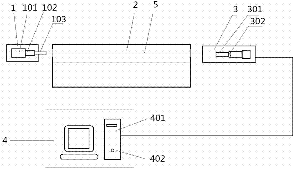
[0027] figure 1 It is a schematic diagram of the overall structure of the system for performing on-line monitoring of the condition of the inner wall surface of the pusher kiln according to the present invention. Such as figure 1 As shown in , the monitoring system according to the present invention mainly includes an active light emitting device 1 , a passive imaging receiving device 3 and a central processing device 4 . The pusher kiln body 2 as the object to be detected is installed horizontally, and on the outer sides of its axial left and right ends, an active light source emitting device 1 ...


PUM

PropertyMeasurementUnit
Wavelengthaaaaaaaaaa

Abstract

The invention discloses a system used for conducting on-line monitoring for pushed slab kiln inner wall surface condition. The system used for conducting the on-line monitoring for the pushed slab kiln inner wall surface condition comprises an active light source emitting device, a passive imaging receiving device and a central processing unit, wherein the active light source emitting device is arranged on the outer side of one end of the pushed slab kiln body and used for producing blue laser beams or green laser beams, and the laser beams penetrate through the kiln body in a manner of covering and lighting the whole pushed slab kiln inner wall surface after being processed through expansion shaping. The passive imaging receiving device is arranged on the outer side of the other end of the kiln body and used for receiving the laser beams from the kiln and producing corresponding detecting images. The central processing unit is used for conducting real-time judgment for the pushed slab kiln inner surface conditions according to the detecting images produced by the passive imaging receiving device, so that the monitoring of the pushed slab kiln inner wall surface condition is achieved. The system used for conducting the on-line monitoring for the pushed slab kiln inner wall surface condition is capable of achieving effective detection for the pushed slab kiln inner wall surface condition with the compact structure and the convenient operation. At the same time, the system has the advantages of being high in automation degree and detection precision, and suitable for on-line detection and the like.

Description

technical field [0001] The invention belongs to the technical field of kiln detection, and more specifically relates to a system for performing on-line monitoring of the condition of the inner wall surface of a pusher kiln. Background technique [0002] The industrial kiln is a device made of refractory materials for calcining materials or firing products. Its working principle is that fuel enters the furnace and burns. Part of the heat emitted is absorbed by the heating medium, and the other part is used to maintain the entire environment in the furnace. temperature. Industrial kilns usually include kiln chambers, combustion equipment, ventilation equipment, and conveying equipment, and can be divided into kiln car kilns, pusher kilns, roller kilns, conveyor belt kilns, and air cushion kilns according to the carrier of the green body. . Among them, the push plate kiln is a continuous tunnel kiln that uses a refractory push plate to transport the product into the kiln for ...

Claims


Application Information

Patent Timeline
IPC IPC(8): G01B11/16G01N21/00G01N21/88
Inventor 陈海峰张云玖
Owner WUHAN JOHO TECH
Why Eureka
Try Eureka