Switch reluctance motor memory sensor model modeling method

A switched reluctance motor, model modeling technology, applied in AC motor control, electronic commutation motor control, instruments, etc., can solve difficult problems such as switched reluctance motor modeling, and achieve cost and real-time, powerful calculation capacity and improve the effect of optimized design

A switched reluctance motor, model modeling technology, applied in AC motor control, electronic commutation motor control, instruments, etc., can solve difficult problems such as switched reluctance motor modeling, and achieve cost and real-time, powerful calculation capacity and improve the effect of optimized design

CN103095191AActive Publication Date: 2013-05-08CHINA UNIV OF MINING & TECH

Image

  • Switch reluctance motor memory sensor model modeling method

Examples


Embodiment Construction

[0011] An embodiment of the present invention will be further described below in conjunction with accompanying drawing:

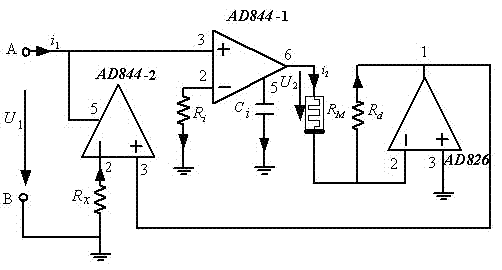
[0012] Such as figure 1 Shown, the switched reluctance motor memristor model modeling method of the present invention:

[0013] a) Using two current conveyors AD844, one operational amplifier AD826 and one memristor, the terminal voltage of the memristor input port A-B is U 1 , the current flowing into the memristor input port A is i 1 ;

[0014] b) Connect the memsensor input port A to the non-inverting input port 3 of the current conveyor AD844-1, connect the non-inverting input port 3 of the current conveyor AD844-1 to the port 5 of the current conveyor AD844-2, and the current conveyor The inverting input port 2 of AD844-1 and the resistor R i Connected to one end of the resistor R i The other end of the current transmitter AD844-1 is grounded, and the port 5 of the current transmitter AD844-1 is connected to the capacitor C i Connected to one e...


PUM


Abstract

Provided is a switch reluctance motor memory sensor model modeling method. A switch reluctance motor memory sensor circuit model is formed by two current conveyors AD844, an operational amplifier AD826, a memristor, a capacitor and three resistors. The modeling method makes a basis for circuit hardware modeling of a switch reluctance motor system model, is beneficial for match direct simulation of a switch reluctance motor system, enables physical phenomena in a simulation system to be similar with an actual switch reluctance motor system, and has important theoretical value and wide application prospects. The modeling method is simple, can improve static and dynamic properties of a system, and achieves real-time simulation and real-time control of the switch reluctance motor system.

Description

technical field [0001] The invention relates to a modeling method for a memristor model of a switched reluctance motor, and is especially suitable for switching reluctance motors with various phase numbers. Background technique [0002] The linear model of the switched reluctance motor ignores nonlinear factors such as magnetic field saturation, so that the phase inductance of the switched reluctance motor is only related to its rotor position angle, but has nothing to do with the magnitude of the phase current. There are large errors in optimization design, quantitative analysis of static and dynamic performance, evaluation of control strategies, etc. The switched reluctance motor body has local magnetic saturation and has a nonlinear magnetic circuit, and its power converter is in the switching mode and has a nonlinear circuit topology. Therefore, the phase inductance of the switched reluctance motor has nonlinear characteristics, not only related to its rotor position ang...

Claims


Application Information

Patent Timeline
08 May 2013
Publication
CN103095191A
IPC
H02P6/00; G06F17/50
CPC
Y02T10/82; G06F17/50; H02P6/00; G06F30/367; H02P25/08
Inventors
陈昊; 梁燕