Water quality detection device and method

A water quality detection and detection cell technology, which is applied to measurement devices, material analysis by electromagnetic means, instruments, etc., can solve the problems of poor measurement accuracy of detection devices, affecting the stability of electrode measurement, and inaccurate addition volume, etc. Good accuracy, strong electrode activity durability, ensuring long-term unchanged effect

Active Publication Date: 2015-04-01
FOCUSED PHOTONICS
View PDF6 Cites 2 Cited by
  • Summary
  • Abstract
  • Description
  • Claims
  • Application Information

AI Technical Summary

Problems solved by technology

[0003] 1. When the reagent enters from the bottom of the flow cell, the bubbles contained in the reagent are easy to adhere to the surface of the working electrode, thus affecting the stability of the electrode measurement
[0004] 2. During the measurement interval of the instrument, the detection electrode is exposed to the air, which easily leads to a rapid decline in electrode activity, and frequent maintenance of the electrode is required to restore its activity, which increases the amount of instrument maintenance
However, the small volume of standard addition liquid is easy to remain on the inner surface of the pipeline during the transportation process, and the effective standard addition volume is inaccurate, resulting in poor measurement accuracy of the detection device

Method used


Image

  • Water quality detection device and method
  • Water quality detection device and method
  • Water quality detection device and method

Examples


Embodiment 1

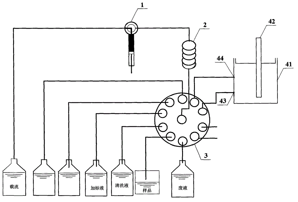
[0044] figure 1 Schematically provides a simplified structural diagram of the water quality detection device of the embodiment of the present invention, as figure 1 As shown, the water quality detection device includes:

[0045] An electrode 42 and a detection cell 41 , the electrode 42 is set in the detection cell 41 . Both the electrodes 42 and the detection cell 41 are prior art in this field, and will not be repeated here.

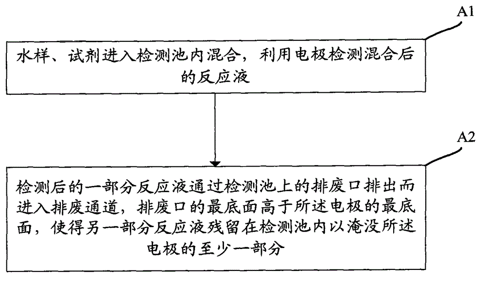
[0046] A liquid discharge port 43, the liquid discharge port 43 is arranged on the detection pool 41, and the bottom surface of the liquid discharge port 43 is higher than the bottom surface of the electrode 42, so that the liquid in the detection pool 41 cannot be drained. for protecting the electrodes 42;

[0047] A liquid discharge channel, the liquid discharge channel communicates with the liquid discharge port.

[0048] The first switching unit 3, the first switching unit 3 is used to selectively communicate the drain port with the water sampl...

Embodiment 2

[0055] image 3 Schematically provides a simplified structural diagram of the water quality detection device of the embodiment of the present invention, as image 3 As shown, the water quality detection device includes:

[0056]An electrode 42 and a detection cell 41 , the electrode 42 is set in the detection cell 41 . Both the electrodes 42 and the detection cell 41 are prior art in this field, and will not be repeated here.

[0057] A liquid discharge port 43, the liquid discharge port 43 is arranged on the detection pool 41, and the bottom surface of the liquid discharge port 43 is higher than the bottom surface of the electrode 42, so that the liquid in the detection pool 41 cannot be drained. for protecting the electrodes 42;

[0058] a liquid discharge channel, the liquid discharge channel is in communication with the liquid discharge port;

[0059] A liquid inlet 44, the liquid inlet 44 is arranged on the detection pool, and the bottom surface of the liquid inlet 44...

Embodiment 3

[0072] An application example of the water quality detection device and method according to Embodiment 1 of the present invention. In this application example, the simultaneous detection of lead, cadmium, copper and zinc is carried out by using the same position mercury plating and the standard comparison method.

[0073] Figure 5 Schematically provides a schematic structural diagram of the detection pool of the embodiment of the present invention, as Figure 5 As shown, in order to reduce the residual solution, the inner bottom of the detection cell 41 is made trapezoidal or hemispherical.

[0074] The specific detection method is as follows: through the switching of the first switching unit, the work of the suction unit and the quantitative unit, the quantified reagent and sample enter the detection pool 41 from the hole 43 respectively, and the reagent is mixed with the sample under the agitation of the stirrer, and the detection unit Detect the mixed reaction solution t...


PUM


Abstract

The invention provides a water quality detection device. The water quality detection device comprises an electrode and a detection cell, as well as a liquid drain hole formed in the detection cell, and a liquid drain passage communicated with the liquid drain hole, wherein the lowermost surface of the liquid drain hole is higher than the lowermost surface of the electrode. The water quality detection device provided by the invention has the advantages of reliable and stable electrode, long work time, and so on.

Description

technical field [0001] The invention relates to water quality analysis, in particular to a water quality detection device and method. Background technique [0002] Electrochemical detection is one of the main analysis methods used by online water quality analyzers. In order to reduce reagent residue, this type of analyzer generally designs the solution inlet and outlet at the bottom of the flow cell, and the electrodes are inserted into the flow cell from top to bottom. This kind of flow cell structure and electrode installation method has the following disadvantages: [0003] 1. When the reagent enters from the bottom of the flow cell, the bubbles contained in the reagent are easy to adhere to the surface of the working electrode, thus affecting the stability of the electrode measurement. [0004] 2. During the measurement interval of the instrument, the detection electrode is exposed to the air, which easily leads to a rapid decline in electrode activity, and frequent ma...

Claims


Application Information

Patent Timeline
Patent Type & Authority Patents(China)
IPC IPC(8): G01N27/416
Inventor 褚衍龙项光宏吕国文
Owner FOCUSED PHOTONICS
Why Eureka
Try Eureka