Valve replacement devices, delivery device for a valve replacement device and method of production of a valve replacement device

A valve replacement and delivery device technology, applied in the direction of heart valves, medical science, stents, etc., can solve problems such as damage

Inactive Publication Date: 2013-05-15
SYMETIS
View PDF10 Cites 32 Cited by
  • Summary
  • Abstract
  • Description
  • Claims
  • Application Information

AI Technical Summary

Problems solved by technology

[0007] Collapsing some known stented valves to a diameter smaller than 18 Fren

Method used


Image

  • Valve replacement devices, delivery device for a valve replacement device and method of production of a valve replacement device
  • Valve replacement devices, delivery device for a valve replacement device and method of production of a valve replacement device
  • Valve replacement devices, delivery device for a valve replacement device and method of production of a valve replacement device

Examples


Embodiment Construction

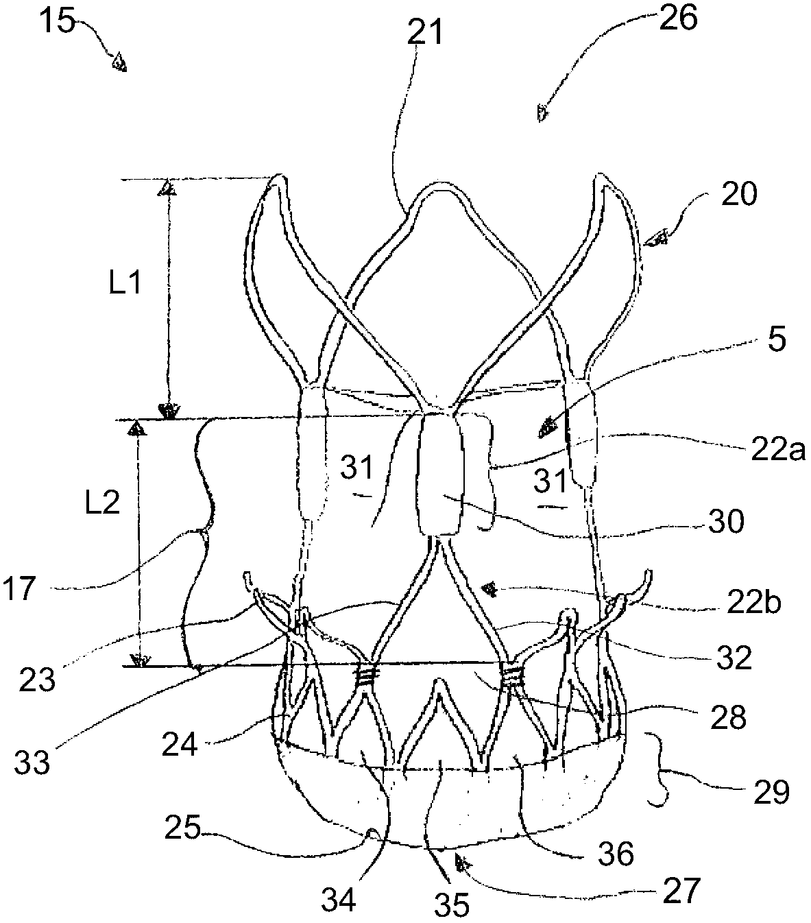
[0103] figure 1 A preferred embodiment of a valve replacement device 15 according to the invention is shown. The valve replacement device 15 is adapted for insertion via a transfemoral approach, but the device may also typically be inserted via other transvascular routes or via a transapical approach. The replacement device 15 has a first end 26 , a second end 27 and an intermediate portion 17 , and includes a stent member 20 and a valve member 5 . In this embodiment, said first end 26 is intended to be positioned in the artery, while the second end 27 is intended to be positioned at or towards the ventricle of the patient's heart. When valve replacement device 15 is in place, blood will flow from second end 27 to first end 26 via intermediate portion 17 . Therefore, the portion between the second end 27 and the intermediate portion 17 may also be referred to as an "inflow portion". Thus, the portion between the intermediate portion 17 and the second end 26 is referred to a...


PUM


Abstract

A device for heart valve replacement comprises a valve component having at least two valve leaflets preferably made of pericardium tissue. Each valve leaflet includes at least two tabs. The device further includes a stent component configured to be radially compressible into a compressed state and expandable into a functional state. The stent component comprises a first end, a second end and at least one intermediate section arranged between said first and said second end. The intermediate section has at least two commissural posts generally aligned parallel to an axis spanning from the first end to the second end. The commissural posts are formed in the shape of a wishbone.

Description

technical field [0001] The present invention relates to a device for valve replacement, especially aortic valve replacement. Furthermore, the present invention also relates to a delivery device for a valve replacement device and to a method of producing a valve replacement device. Valve replacement devices may also refer to stented valves or valve stents. Background technique [0002] Conventional methods of heart valve replacement require a relatively large opening in the patient's sternum ("sternotomy") or chest cavity ("thoracotomy") in order to allow the surgeon access to the patient's heart. Additionally, these methods require stopping the patient's heart and require cardiopulmonary bypass (ie, the use of a cardiopulmonary bypass machine to oxygenate and circulate the patient's blood). In recent years, efforts have been made to insert through a small skin incision either by a transvascular approach (delivery of the new valve through the femoral artery) or by a transap...

Claims


Application Information

Patent Timeline
IPC IPC(8): A61F2/24
CPCA61F2002/9505A61F2/2418A61F2220/0075A61F2230/0013A61F2/2412A61F2/2415A61F2/2436A61F2230/001A61F2240/001A61F2250/0039
Inventor Y·比阿迪拉S·迪拉罗耶F·隆巴迪J-L·赫弗堤
Owner SYMETIS
Why Eureka
Try Eureka