
Plate-and-frame filter press

A plate-and-frame filter press and plate-and-frame technology are applied in the direction of filtration and separation, separation methods, chemical instruments and methods, etc., which can solve the problems of cumbersome operation, reduced efficiency, and high maintenance costs, so as to prevent environmental pollution, prolong service life, The effect of high cleaning efficiency

Inactive Publication Date: 2013-05-22
王焕坤
View PDF10 Cites 15 Cited by
  • Summary
  • Abstract
  • Description
  • Claims
  • Application Information

AI Technical Summary

Problems solved by technology

In the existing hydraulic compression, the hydraulic station pushes the compression plate to compress the filter plate in one direction through the hydraulic cylinder components on the frame. Since the hydraulic cylinder components push and compress the filter plate in one direction, the output of one compression is low. , the same energy consumption will easily lead to energy waste
[0003] In order to improve the filter press effect, reduce the water content after the press filter, and improve the work efficiency, the current filter press is equipped with a spring mechanism between the main board and the sub-frame. However, the use of the spring mechanism makes this patent have the following disadvantages: 1) The spring mechanism is set between the main board and the sub-frame, which generates tension on the main board and the sub-frame on both sides. If too many springs are used, the resistance will be large during the filter pressing process, which will increase the workload of the hydraulic pressing device and reduce the efficiency. , less materials for one-time filter press, 2) Due to the different tension of each spring, the plate and frame cannot be kept balanced and advanced during the filter press process, the error is large, it is easy to deform the plate and frame, and the sludge moisture content after pressing is high, 3) As the number of springs increases with the use of the spring, the spring mechanism will undergo permanent deformation. If the spring at a certain position between the main board and the sub-frame is deformed, during the filter press process, the hydraulic cylinder parts will push the compression plate to squeeze the plate frame, and the spring will The deformation of the main board and the sub-frame causes uneven force at each angle, which easily leads to deformation of the board and frame. In severe cases, even material leakage prevents normal work. According to actual production experience, the spring needs to be replaced after a period of time, but the spring is set in Between the main board and the sub-frame, replacing the spring requires dismantling the entire board and frame device, which is difficult to replace and expensive to repair
But the structure is complicated, the cost is high, and the operation is cumbersome

Method used


Image

  • Plate-and-frame filter press
  • Plate-and-frame filter press
  • Plate-and-frame filter press

Examples


Embodiment 1

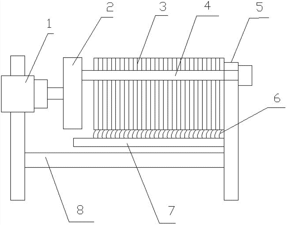
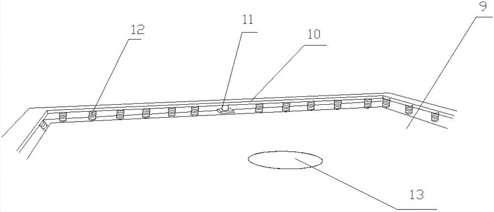
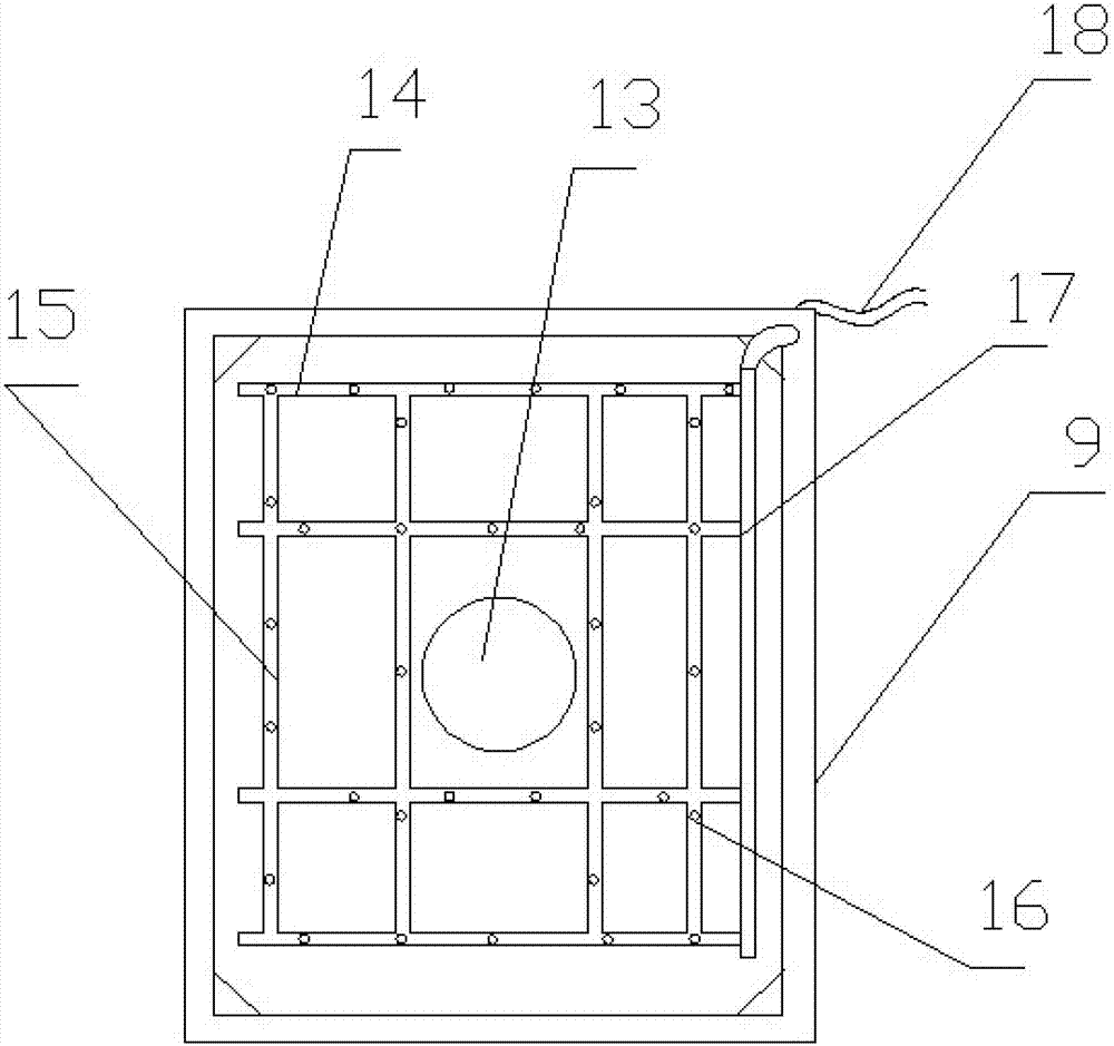
[0044] A plate and frame filter press with a structure such as figure 1 , figure 2 As shown, it includes a bracket 8, two beams 4 mounted on the bracket 8, and a hydraulic pressing device 1 arranged on the frame. A pushing plate 2, a blocking plate 5, and a pushing plate 2 are fixedly arranged between the two beams 4 Several filter plates and plate frames are arranged between the blocking plate 5 and the several filter plates and plate frames to form a filter frame group 3. The plate frame 9 and the filter plate 20 form a filter cavity, and a filter cloth is set above the filter cavity (Figure Not shown), one side of each plate frame 9 has a planar structure, and the other side has a protruding frame and a recessed internal structure. On one side of the plane of the plate frame 9, a plate frame extruding balance frame 10 is provided, and the plate frame 9 and Springs 12 are provided between the plate frame extrusion balance frame 10, and small hydraulic cylinders 11 are respect...

Embodiment 2

[0059] In the plate and frame filter press described in the same embodiment 1, a plate frame stabilizing wheel 30 is also provided on the side of the plate frame and the plate frame extrusion stabilization frame, and the structure is as Picture 10 , Picture 11 As shown, the frame stabilizing wheel 30 includes a pulley 32, a guide rail 31, and a pulley bracket 33. The guide rail 31 is fixed on the side wall of the board frame 9. The pulley 32 is arranged on the guide rail 31 and can slide along the guide rail. The pulley bracket 33 is a rectangular flat plate, fixedly connected to the side wall of the plate frame extrusion stability frame 10, the pulley bracket 33 is two pieces, symmetrically arranged on both sides of the guide rail 31, the pulley bracket 33 is provided with pulley adjustment grooves, on both sides of the pulley The ends of the pulley shafts are respectively inserted into the pulley adjustment grooves. The plate frame squeeze stabilization frame moves along th...


PUM


Abstract

The invention relates to a plate-and-frame filter press which comprises a support, two cross beams and a hydraulic compressing device arranged on the support, wherein a push plate, a stop plate and a plate-and-frame group are arranged between the two cross beams, one side of each plate frame is in a plane structure, another side of each plate frame is a frame convex, each plate frame has a concave structure inside, one side of each plate frame plane is provided with a plate frame extruding balance beam, a spring and a small hydraulic cylinder are arranged between each plate frame and each plate frame extruding balance beam, a hydraulic oil opening is arranged on a small hydraulic cylinder body, the hydraulic oil opening is connected with a hydraulic oil support pipe, and a hydraulic oil branch pipe on each plate frame is communicated with a hydraulic oil main pipe on each plate frame. The position except a material inlet on the surface at one side of each plate frame is provided with an automatic filter cloth cleaning device. The plate-and-frame filter press is simple in structure, each plate frame can be synchronously pushed in the process of filter-press, the plate frames can be compacted with one another, the material can not be lost, the plate-and-frame filter press is high in filter-press efficiency, the workload of the hydraulic compressing device can be effectively reduced, each plate frame can not deform or be damaged, and the plate-and-frame filter press has a function for cleaning a filter cloth on line.

Description

Technical field [0001] The invention relates to a plate and frame filter press, which belongs to the technical field of solid-liquid separation equipment. Background technique [0002] The plate and frame filter press is a kind of intermittent solid-liquid separation equipment, which is light, flexible and reliable. It is composed of filter plates and filter frames arranged to form a filter chamber. Under the action of a feed pump, the material and liquid are transported to each The filter chamber separates the solid and liquid through the filter medium. Compared with other solid-liquid separation equipment such as centrifuges, the plate and frame filter press has the advantages of low investment, energy saving, and safety. It is widely used in chemicals, dyes, petroleum, ceramics, medicine, food, smelting and various industries. Sewage treatment etc. The compression method of the filter press has three forms: manual compression (small size), mechanical compression and hydrauli...

Claims


Application Information

Patent Timeline
IPC IPC(8): B01D25/21
Inventor 王毅王焕坤
Owner 王焕坤
Learn More