External catalytic cracking heater with pre-distributed particles

An external heat extractor, catalytic cracking technology, applied in catalytic cracking, fluidized bed heat exchanger, cracking and other directions, can solve the problem of not completely solving the problem of particle erosion of heat exchange tubes

Inactive Publication Date: 2013-05-22
CHINA UNIV OF PETROLEUM (BEIJING)
View PDF13 Cites 10 Cited by
  • Summary
  • Abstract
  • Description
  • Claims
  • Application Information

AI Technical Summary

Problems solved by technology

In general, although the above-mentioned patents can improve the reliability of the dense-phase descending external heat extractor to a certain extent, they cannot effectively improve the uneven heat extraction load of t

Method used


Image

  • External catalytic cracking heater with pre-distributed particles
  • External catalytic cracking heater with pre-distributed particles
  • External catalytic cracking heater with pre-distributed particles

Examples


Embodiment 1

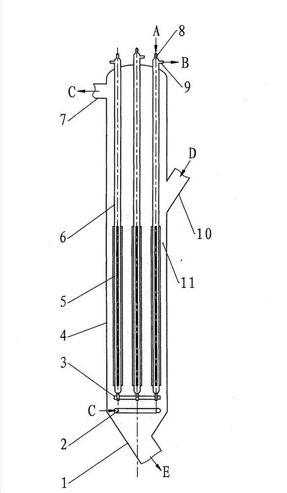
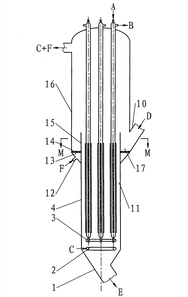
[0034] figure 2 Provide a kind of typical type of catalytic cracking external heat extractor of the present invention, it and figure 1 The difference of the common external heat extractor shown is: the hot catalyst particle D coming in from the catalyst inlet (10) in the middle part of the external heat extractor (4) first enters in an annular fluidized bed (17), and the hot catalyst particle D After entering the annular fluidized bed (17), it is rapidly dispersed on the cross section of the annular fluidized bed (17) under the action of the fluidizing wind F, and then from the inner side wall (15) of the annular fluidized bed (17). The upper edge overflows into the dense phase fluidized bed (11). The fluidizing air F first enters the fluidizing air pre-distribution cavity (13) from the gas inlet (12), and then enters the annular fluidized bed (17) through the gas distribution plate (14) arranged at the bottom. The fluidizing gas C of the dense-phase fluidized bed (11) is i...

Embodiment 2

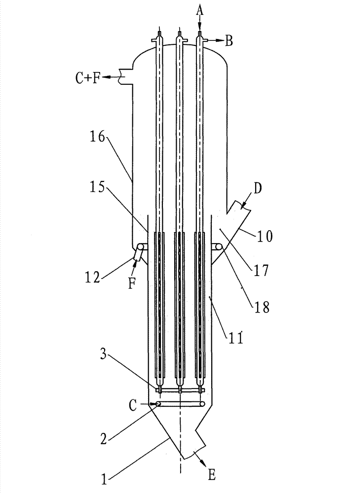
[0037] image 3 Another typical type of the catalytic cracking external heat extractor of the present invention is given. Overall, the design and figure 2 The shown external heat extractors are basically the same, except that a gas distribution pipe (18) is arranged at the bottom of the annular fluidized bed (17) instead of figure 2 Gas distribution plate (14) shown in . In contrast, the design is more figure 2 The shown scheme structure is simpler.

Embodiment 3

[0039] Figure 4 Provide another typical type of catalytic cracking external heat extractor of the present invention, this design and image 3 The shown external heat extractor is basically the same, and the difference is the design of the enlarged section (16), and figure 2 and image 3 The difference in the structure of the external heat extractor shown is that the enlarged section (16) does not extend all the way to the top of the external heat extractor (4) in this design, but only a partial section, and the diameter of the upward external heat extractor (4) It transitions to the same diameter as the dense-phase fluidized bed (11), and this structure is more suitable for the transformation of existing external heat extractors.


PUM


Abstract

The invention discloses an external catalytic cracking heater with pre-distributed particles and is suitable for a catalytic cracking device in an oil refinery. The external catalytic cracking heater is characterized in that a plurality of unit type heat exchange tubes (6) with independent water inlets and water outlets are arranged inside an external heater (4); the heat exchange tubes (6) extend from the top to the bottom of the external heater (4), and the bottom of the external heater is provided with a guide bracket (2) which limits transverse swing of the heat exchange tubes (6); the lower parts of the heat exchange tubes (6) are immersed in a dense-phase fluidized bed (11) at the bottom of the external heater (4); hot catalyst particles entering from a catalyst inlet (10) in the middle of the external heater (4) enter an annular fluidized bed (17), and the hot particles uniformly flow into the dense-phase fluidized bed (11) from the upper edge of a side wall (15) on the inner side of the annular fluidized bed (17) or an overflow notch (19) formed in the side wall (15) on the inner side by utilizing the particle pre-distribution function of the annular fluidized bed (17); the hot particles are contacted and cooled with the side wall of the heat exchange tubes (6) and flow out of a catalyst outlet (1) at the bottom of the external heater (4) in the dense-phase fluidized bed (11); and fluidized gas in the dense-phase fluidized bed (11) is introduced from a bottom gas distributor (2), and the fluidized gas which passes through the dense-phase fluidized bed (11) and the fluidized gas in the annular fluidized bed (17) are mixed to enter a dilute phase space of a catalytic cracking device regenerator through a gas outlet (7) formed on the top of the external heater (4).

Description

technical field [0001] The invention relates to an external heat extractor for catalytic cracking whose particles can be pre-distributed, and belongs to the technical field of petroleum processing. technical background [0002] Fluid catalytic cracking is one of the core production processes of light oil products in domestic oil refineries. It uses molecular sieve catalysts to crack low-value heavy raw materials (wax oil or residual oil) into high-value light oil products, such as gasoline , diesel and liquefied petroleum gas, etc. In China, the core position of fluidized catalytic cracking process is more prominent, it produces 70-80% of commercial gasoline, about 30% of commercial diesel and about 30% of propylene. [0003] A major feature of the catalytic cracking process is the system heat balance, that is, the heat required for the endothermic cracking reaction process is provided by the exothermic coke regeneration process. With the heavy and inferior quality of cata...

Claims


Application Information

Patent Timeline
IPC IPC(8): C10G11/18F28D13/00
Inventor 张永民禹淞元张新国姚秀颖卢春喜臧泉龙韩霄
Owner CHINA UNIV OF PETROLEUM (BEIJING)
Why Eureka
Try Eureka