Blowing desulfurization method for molten iron of torpedo ladle
A torpedo tank and torpedo tank technology are applied in the field of molten iron pretreatment, which can solve the problems of high sulfur return in molten iron, not seen, and insufficient reliability, and achieve the effects of high desulfurization efficiency, large production capacity and convenient implementation.
- Summary
- Abstract
- Description
- Claims
- Application Information
AI Technical Summary
Problems solved by technology
Method used
Image
Examples
Embodiment 1
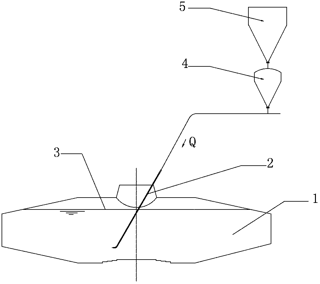
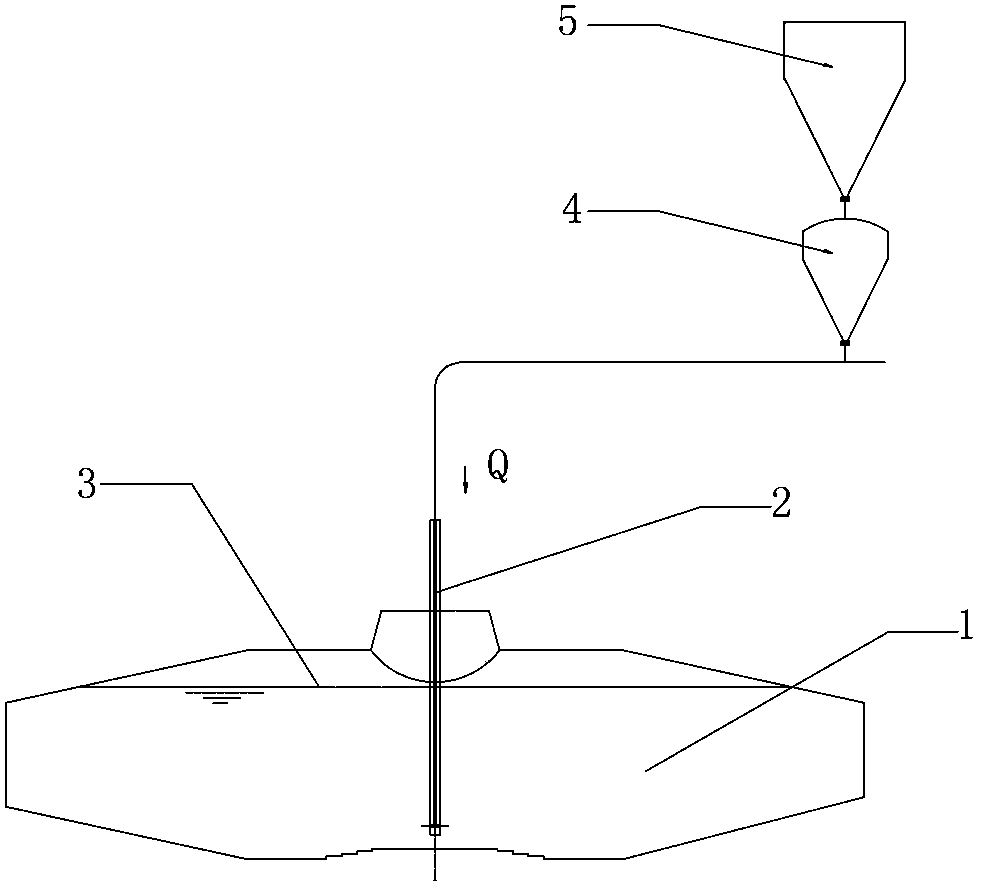
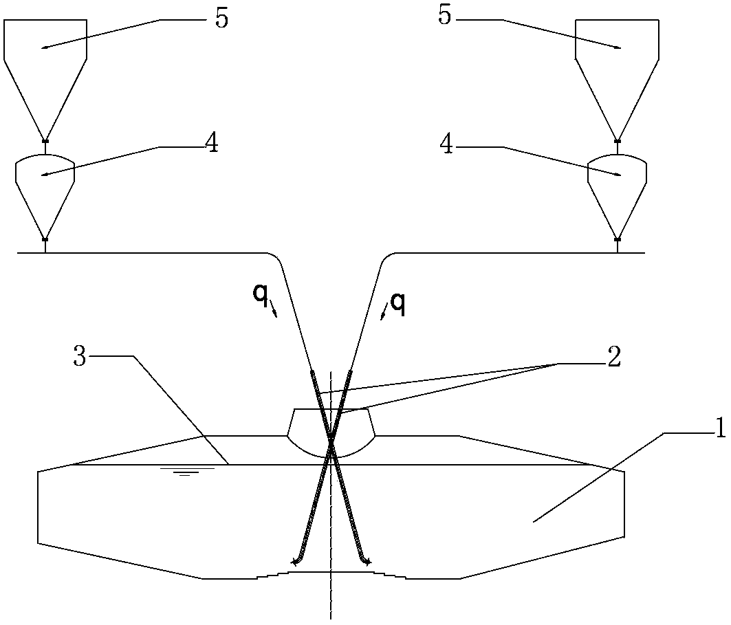
[0029] see Figure 3 to Figure 5 , In the torpedo tank molten iron injection desulfurization method of the present invention, a torpedo tank 1, an L-shaped spray gun 2, a blow tank 4 and a storage tank 5 are involved.
[0030] The torpedo tank molten iron injection desulfurization method includes the following steps in turn: molten iron enters the station, temperature measurement and sampling, lower gun injection, adding thin slag modifier, starting gun and finishing injection, temperature measurement and sampling, adding heat preservation agent and The molten iron goes out of the station, wherein, in the spraying step of the lower gun, two L-shaped spray guns 2 are inserted into the torpedo tank 1 at an angle to spray desulfurization at the same time. End walls 1.1.
[0031] Two L-shaped spray guns 2 are symmetrically arranged around the length symmetry plane 1.2 of the torpedo tank, the angle α between the axis of the L-shaped spray gun 2 and the length symmetry plane 1.2 of ...
Embodiment 2
[0033] see image 3 , Figure 5 and Image 6 , the present embodiment is basically the same as Embodiment 1, except that the included angle α between the axis of the L-shaped spray gun 2 and the length symmetry plane 1.2 of the torpedo tank is 15°, and the downward inclination angle β of the spray port 2.1 axis of the L-shaped spray gun 2 It is 3 °, and the center distance d of the nozzles 2.1 of the two L-shaped spray guns 2 is the same as the diameter D of the mouth of the torpedo tank 1.3, that is, d=D. The distance between the intersection point of the two L-shaped spray guns 2 and the molten iron level 3 is H, and the distance from the torpedo tank mouth 1.3 to the molten iron level 3 is Hi. In this embodiment, the relationship between the two is: H=Hi−0.3D. The distance h between the blowing port 2.1 of the L-shaped spray gun 2 and the bottom 1.4 of the torpedo tank is 250mm, and the desulfurizing agent injection flow q of each L-shaped spray gun 2 is the desulfurizing...
Embodiment 3
[0035] see image 3 and Figure 7 , the present embodiment is basically the same as Embodiment 1, except that the included angle α between the axis of the L-shaped spray gun 2 and the length symmetry plane 1.2 of the torpedo tank is 30°, and the downward inclination angle β of the spray port 2.1 axis of the L-shaped spray gun 2 It is 0 °, and the distance d between the centers of the nozzles 2.1 of the two L-shaped spray guns 2 is 2.5 times of the diameter D of the mouth of the torpedo tank 1.3, that is, d=2.5D. The distance between the intersection point of the two L-shaped spray guns 2 and the molten iron level 3 is H, and the distance between the mouth of the torpedo tank 1.3 and the molten iron level 3 is Hi. In this embodiment, the relationship between the two is: H=Hi. The distance h between the injection port 2.1 of the L-shaped spray gun 2 and the bottom 1.4 of the torpedo tank is 200mm, and the desulfurizing agent injection flow q of each L-shaped spray gun 2 is the ...
PUM
 Abstract
Description
Claims
Application Information
 - R&D
- Intellectual Property
- Life Sciences
- Materials
- Tech Scout
- Unparalleled Data Quality
- Higher Quality Content
- 60% Fewer Hallucinations
Browse by: Latest US Patents, China's latest patents, Technical Efficacy Thesaurus, Application Domain, Technology Topic, Popular Technical Reports.
© 2025 PatSnap. All rights reserved.Legal|Privacy policy|Modern Slavery Act Transparency Statement|Sitemap|About US| Contact US: help@patsnap.com


