Full-automatic detecting system for power quality monitoring devices

A technology for power quality monitoring and equipment testing, which is applied in the direction of measuring electrical variables, measuring electricity, and measuring devices, and can solve problems such as inconsistency between the functions of power quality monitoring equipment and regulations, human errors, low work efficiency, and inconsistent sources of power quality standards , to facilitate retrieval and query, ensure data security, and shorten detection time

Inactive Publication Date: 2013-05-22
ELECTRIC POWER RES INST OF GUANGDONG POWER GRID +1
View PDF6 Cites 19 Cited by
  • Summary
  • Abstract
  • Description
  • Claims
  • Application Information

AI Technical Summary

Problems solved by technology

This detection method has a large workload, takes a long time, and will inevitably lead to human error and low work efficiency.
In response to this situation, it is necessary to consider the research of a fully automatic power quality monitoring equipment detection system, which can realize operations such as fully automatic control and automatic calculation of errors in the power quality standard source and the monitored monitoring equipment during the detection process, and greatly reduce the power quality during the detection process. The automatic detection system also needs to take into account the fact that the current power quality monitoring equipment is still based on the manufacturer's private regulations, as well as the inconsistent testing specifications and testing content in various regions, the inconsistency between the functions of power quality monitoring equipment and the regulations, and the source of power quality standards. Inconsistency and other status quo, it is necessary to achieve compatibility with the above differences

Method used


Image

  • Full-automatic detecting system for power quality monitoring devices
  • Full-automatic detecting system for power quality monitoring devices
  • Full-automatic detecting system for power quality monitoring devices

Examples


Embodiment Construction

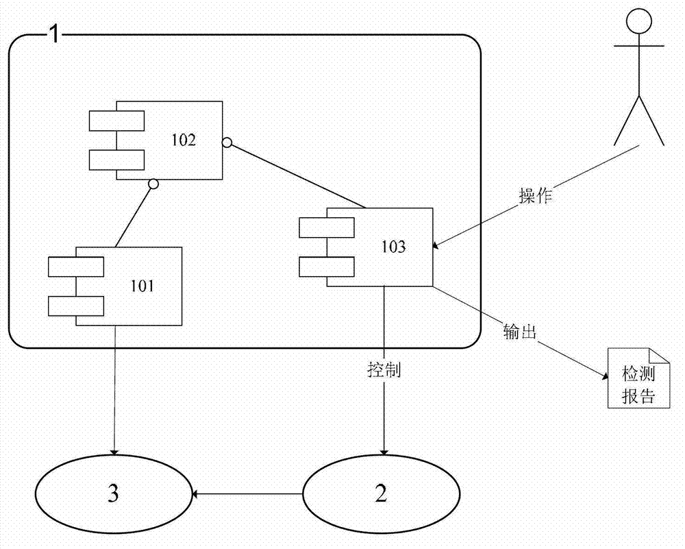
[0023] Combine below figure 1 The present invention will be further described with specific embodiments.

[0024] see figure 1 , the embodiment of the automatic power quality monitoring equipment detection system of the present invention is mainly composed of a host computer detection system 1, a standard source 2 and a monitored monitoring device 3. The host computer detection system 1 includes a data acquisition module 101, a data storage module 102 and Detection control module 103; the monitored monitoring equipment is connected to the standard source through the test signal line, the monitored monitoring equipment is connected to the upper computer through Ethernet, and the standard source is connected to the upper computer through the GPIB bus to form a closed-loop control system. The standard source adopts the Fluke6100A power source produced by Fluke Company. The system uses one Fluke6100A as the main engine and two Fluke6100A as auxiliary machines to simulate the thre...


PUM


Abstract

A full-automatic detecting system for power quality monitoring devices comprises an upper computer detecting system and a standard source. The upper computer detecting system comprises a data acquisition module, a data storage module and a detecting control module, a detected monitoring device is connected with the standard source by a testing signal line and is connected with the upper computer detecting system by an Ethernet, and the standard source and the upper computer detecting system are connected with each other by a GPIB (general purpose interface bus) to form a closed-loop control system. The power quality monitoring device can be fully automatically detected by means of simple connection and configuration during detection. The full-automatic detecting system has the advantages that the detection time is shortened, the detection efficiency is improved, errors caused by human factors are prevented, the extension compatibility is sufficiently considered in order to gain support of detection specifications in different regions, different standard sources and the detected monitoring devices, and novel standard sources and novel detected monitoring devices can be quickly connected into the full-automatic detecting system on the basis of a detection scheme template and the UAPI (uniform application program interface) technology.

Description

technical field [0001] The invention relates to a fully automatic detection device for electric power equipment, in particular to a fully automatic power quality monitoring equipment detection system. Background technique [0002] As more and more high-end power quality monitoring equipment is applied to the power grid, and the power quality management mechanism of the power grid gradually matures, the technical management departments at all levels of the power grid have an increasing workload in testing power quality monitoring equipment. The detection of power quality monitoring equipment is generally divided into three types: type test and network inspection of new type equipment, initial inspection of equipment purchased for new projects, and regular inspection after equipment is put into use. At present, the power grid in some areas requires the implementation of the policy of "first inspection and every inspection" for power quality monitoring equipment, and manual ins...

Claims


Application Information

Patent Timeline
Patent Type & Authority Applications(China)
IPC IPC(8): G01R31/00
Inventor 王玲徐柏榆盛超陈晓科邓志李玎刘宁黄俊王昕杨昊睿叶李花
Owner ELECTRIC POWER RES INST OF GUANGDONG POWER GRID
Why Eureka
Try Eureka