Method for producing a piston for an internal combustion engine and piston for an internal combustion engine

A manufacturing method and internal combustion engine technology, applied in the direction of pistons, manufacturing tools, machines/engines, etc., can solve problems such as inability to achieve welded connections, and achieve the effect of improving welded connections

Inactive Publication Date: 2013-05-22
MAHLE INT GMBH
View PDF7 Cites 4 Cited by
  • Summary
  • Abstract
  • Description
  • Claims
  • Application Information

AI Technical Summary

Problems solved by technology

[0003] In this method, after the induction coil is removed, the mating surface starts to cool down, so an optimal solder connection cannot be achieved

Method used


Image

  • Method for producing a piston for an internal combustion engine and piston for an internal combustion engine
  • Method for producing a piston for an internal combustion engine and piston for an internal combustion engine
  • Method for producing a piston for an internal combustion engine and piston for an internal combustion engine

Examples


Embodiment Construction

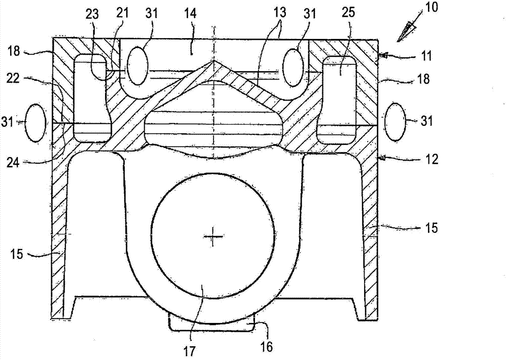
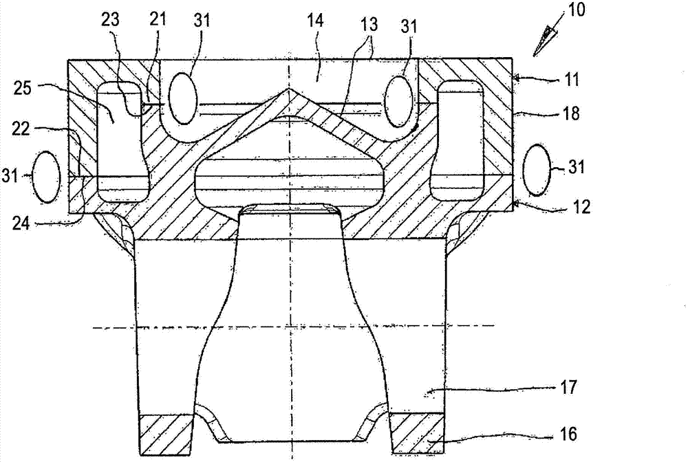
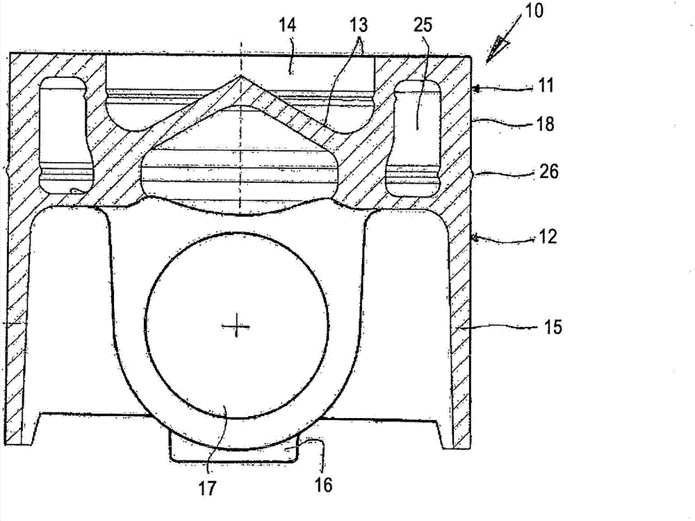
[0030] Figures 1 to 4 A first embodiment of the method according to the invention according to the piston 10 is shown. The piston 10 in this embodiment is a two-part box piston with surrounding cooling channels. The invention is of course also applicable to other piston types.

[0031] The piston 10 is composed of a piston upper part 11 and a piston lower part 12, which can be made of steel or cast iron by casting or forging. The piston 10 has a piston bottom 13 with a combustion chamber cavity 14 , wherein the piston bottom 13 and the combustion chamber cavity 14 are partly formed by the piston upper part 11 and partly by the piston lower part 12 . The fire lands and annular grooves along the outer wall region 18 are not shown for reasons of visibility. The lower piston part 12 has a piston skirt 15 and a piston hub 16 with hub bores 17 for receiving piston bolts (not shown).

[0032] The upper piston part 11 has an inner abutment surface 21 and an outer abutment surface...


PUM


Abstract

The invention relates to a method for producing a piston (10, 110, 210) for an internal combustion engine, characterized by the following steps: a) producing an upper piston part (11, 111, 211) having at least one joining surface (21, 22; 121, 122), b) producing a lower piston part (12, 112, 212) having at least one joining surface (23, 24; 123, 124), c) establishing a direct contact between the at least one joining surface (21, 22; 121, 122) of the upper piston part (11, 111, 211) and the at least one joining surface (23, 24; 123, 124) of the lower piston part (12, 112, 212), d) heating the upper piston part (11, 111, 211) and the lower piston part (12, 112, 212) in the region of the joining surfaces (21, 23; 22, 24; 121, 123; 122, 124) brought in direct contact by induction or by a direct current flow through the joining surfaces (21, 23; 22, 24; 121, 123; 122, 124), and (e) connecting the upper piston part (11, 111, 211) and the lower piston part (12, 112, 212) to form a piston (10, 110, 210) by means of a pressing process and optionally finishing the piston (10, 110, 210).

Description

technical field [0001] The invention relates to a method of manufacturing a piston for an internal combustion engine. Background technique [0002] Such methods are described, for example, in document US Pat. No. 6,825,450 B2. The upper piston part and the lower piston part are joined together by induction welding, wherein an induction coil is placed between the joining surfaces of the upper piston part and the lower piston part. After heating the joint surfaces, the induction coil is removed and the weld is produced. [0003] In this method, after the induction coil is removed, the mating surfaces start to cool down, so that an optimal solder connection cannot be achieved. Furthermore, the method must be carried out in a protective atmosphere in order to avoid adverse effects or adverse changes of the heated joining surfaces due to reactions with oxygen in the air. Contents of the invention [0004] It is an object of the present invention to provide a method for produ...

Claims


Application Information

Patent Timeline
Patent Type & Authority Applications(China)
IPC IPC(8): B23P15/10B23K11/04B23K20/02F02F3/00F02F3/22B23K13/06
CPCB23K2203/04B23K20/227B23K20/129B23K13/015B23K2201/003B23K20/24B23K20/12B23K2203/06B23P15/10B23K11/04B23K13/06F02F3/003B23K20/028B23K20/023F02F3/22B23K2101/003B23K2103/04B23K2103/06Y10T29/49256B23K20/02F02F3/00
Inventor 弗兰克·施奈特赖纳·沙普卡尔海因茨·宾
Owner MAHLE INT GMBH
Why Eureka
Try Eureka