Beam-defining clipper, radiation imaging equipment and X-ray radiation field indicating method

A radiation field and beam limiter technology, applied in the field of beam limiters, can solve the problems of high power consumption of the beam limiter, increase risks, increase the dose of radiation leakage, etc., so as to improve the effect of preventing X-ray scattering and radiation leakage, improve the Good effect of filtration uniformity and protection integrity

Active Publication Date: 2013-06-05
SHENZHEN MINDRAY BIO MEDICAL ELECTRONICS CO LTD
View PDF6 Cites 17 Cited by
  • Summary
  • Abstract
  • Description
  • Claims
  • Application Information

AI Technical Summary

Problems solved by technology

[0006] 1) Complex structure, high production and maintenance requirements
The current beam limiter requires the visible light source and the X light source to be mutually imaged through the reflector. However, due to the inconsistency of production and assembly, the position of the visible light source and the reflector needs to be adjustable to meet this requirement. This aspect increases the adjustable structure The complexity of the process increases the precision requirements of processing and assembly. On the other hand, it also increases the factory test and commissioning process and on-site commissioning process, which also increases the risk in the transportation link. It also requires regular maintenance during the maintenance phase, which ultimately increases the processing cost. , design cost, production transportation cost and maintenance cost
[0007] 2) Difficulty in product miniaturization
Because the reflector is between the visible light source and the X-ray radiation field control device, and at a specific angle, there will be a specific distance between the visible light source and the reflector, and at the same time, the X-ray radiation field control device is located at the end far away from the X-ray source. The size and control stroke of the X-ray radiation field control device are also enlarged unnecessarily. General engineers and technicians know through simple analysis that the size of the beam limiter is limited by the scheme itself and cannot be further miniaturized, while the existing beam limiter Increased risk of hitting the patient in clinical applications due to larger size
[0008] 3) There are many hidden dangers of radiation leakage
Since the visible light irradiation area and the X-ray radiation area cannot be blocked by objects, the radiation-proof shell assembly of the existing beam limiter completely surrounds the two. The common solution is t...

Method used


Image

  • Beam-defining clipper, radiation imaging equipment and X-ray radiation field indicating method
  • Beam-defining clipper, radiation imaging equipment and X-ray radiation field indicating method
  • Beam-defining clipper, radiation imaging equipment and X-ray radiation field indicating method

Examples


Embodiment Construction

[0028] The present invention will be further described in detail below through specific embodiments in conjunction with the accompanying drawings.

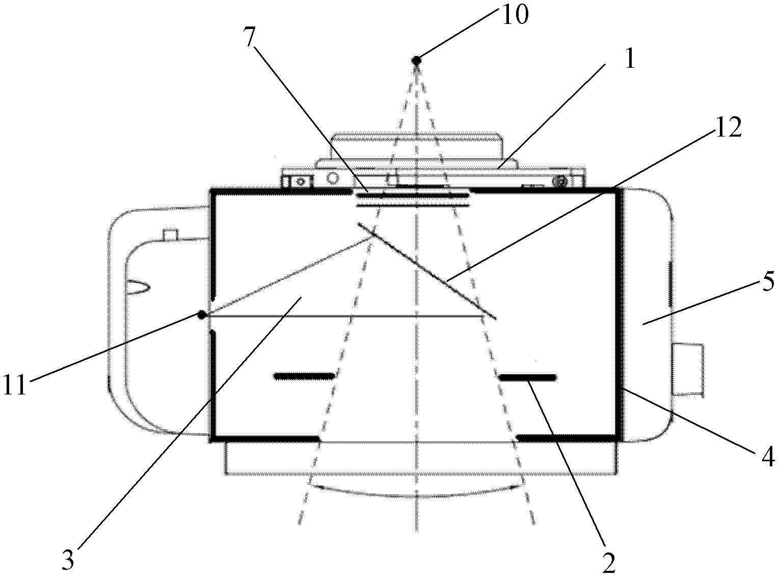
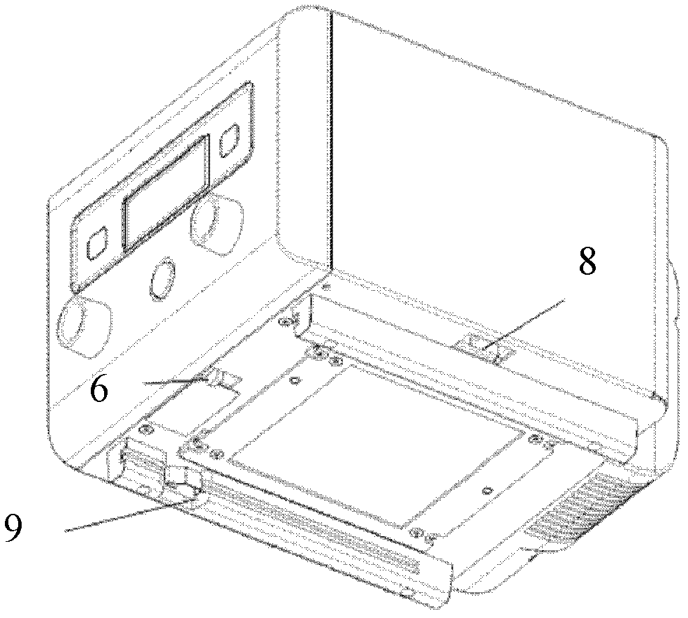
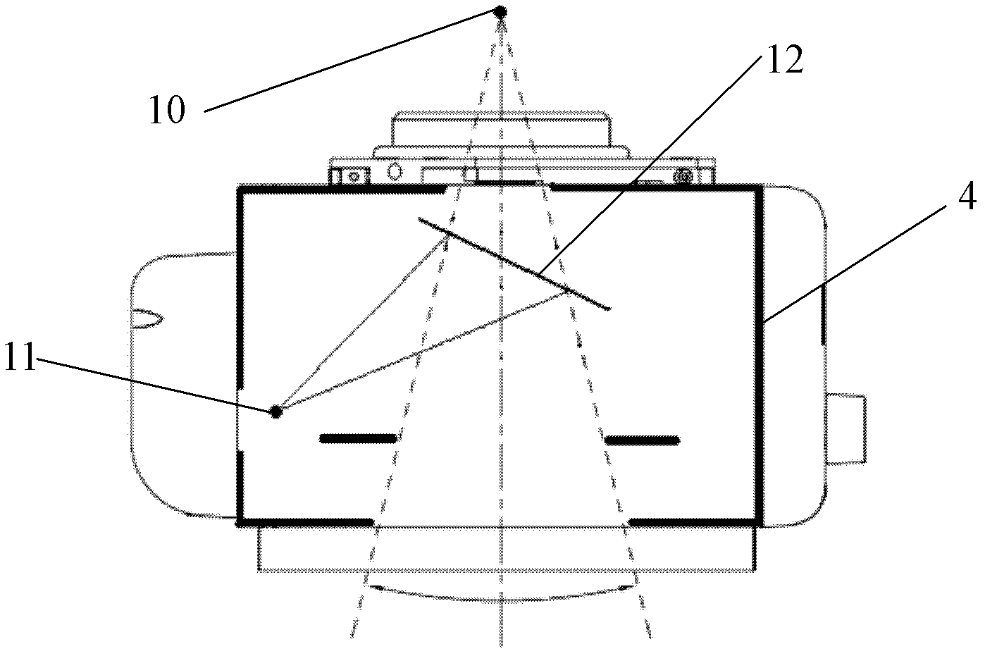
[0029] Such as Figure 4 to Figure 6 As shown, the beam limiter in this embodiment includes an X light source connection device 20 , a radiation shield assembly 21 , an X-ray radiation field control device 22 , a visible light source 23 , a visible light field control device 24 and a control and communication module 30 . The X light source connecting device 20 is used for connecting the X light source 10 (such as an X-ray tube), and the X light source 10 generates X-rays. The radiation shield assembly 21 is used to prevent leakage of X-ray radiation, and it surrounds the area through which X-rays pass. X-rays form a radiation field 25 on the indication surface 14 after passing through the X-ray radiation field control device 22, and the X-ray radiation field control device 22 controls the radiation field 25, such as controlling t...


PUM


Abstract

The invention discloses a beam-defining clipper, radiation imaging equipment and an X-ray radiation field indicating method. The beam-defining clipper, the radiation imaging equipment and the X-ray radiation field indicating method comprise an X-ray radiation field control device used form controlling a radiation field formed by X-rays on an indicating horizon, an anti-radiation shell component used for preventing the radiation leakage of the X-rays, a visible light source used for generating visible light, and a visible optical filed control device used for a visible optical field formed by the visible light on the indicating horizon. The anti-radiation shell component surrounds the areas passed by the X-rays, and the visible optical field and the radiation field are overlapped on the indicating horizon under the control of control and communication devices. The visible optical field control device and the X-ray radiation field control device respectively and independently control the shapes and the positions of the visible optical field and the X-ray radiation field, the position relation of the visible light source and an X-light source is not required, the position of the visible light source can be unadjustable, and therefore a structure is simplified, and meanwhile filtration evenness and the effect of preventing radiation leakage are improved.

Description

technical field [0001] The invention relates to a beam limiter, radiographic equipment and an X-ray radiation field indication method. Background technique [0002] The beam limiter, also known as the beam limiter, is a component in radiological imaging equipment, which is used to control and indicate the X-ray radiation field and prevent X-ray leakage. [0003] Such as figure 1 and figure 2 As shown, the beam limiter generally includes an X-ray tube component connecting device 1 , an X-ray radiation field control device 2 , a light field indicating device 3 , a radiation-proof shell component 4 and a control and communication module 5 . The beam limiter uses an X-ray radiation field control device to control the shape and position of the X-ray radiation field. The light field indicating device 3 uses visible light to simulate the shape and position of the X-ray radiation field, so as to realize the indication of the invisible X-ray radiation field. The light field indi...

Claims


Application Information

Patent Timeline
IPC IPC(8): A61B6/00A61B6/08
Inventor 冯威宋隽涛
Owner SHENZHEN MINDRAY BIO MEDICAL ELECTRONICS CO LTD
Why Eureka
Try Eureka