Combined energy-saving oil cylinder

A combined type and oil cylinder technology, which is applied in the field of energy-saving oil cylinders, can solve the problems of large hydraulic system, system noise, high energy consumption, and increased cost, and achieve the reduction of valve parts and pipeline specifications, simple structure, and low power consumption. Effect of oil pump flow reduction

Inactive Publication Date: 2013-06-05
ZHANGJIAGANG BEIER MACHINERY
View PDF0 Cites 2 Cited by
  • Summary
  • Abstract
  • Description
  • Claims
  • Application Information

AI Technical Summary

Problems solved by technology

[0002] At present, the hydraulic mold clamping mechanism on the known plastic molding machine uses an oil cylinder to perform direct pressure mold clamping. When molding plastic products with a large surface area, a large clamping force is required, so the diameter of the mold clamping cylinder and the hydraulic pressure The pressure of the system is very high, and to produce a certain mold closing speed, the flow of the oil pump must also be large. The power of the oil pump motor is proportional to the pressure and flow of the hydraulic system, so the power of the oil pump motor must be very large. At the same time, the diameters of hydraulic oil circuit boards, hydraulic valves, oil tanks, oil coolers, and pipelines must be increased simultaneously, resulting in a very large hydraulic system, increased costs, and high system noise and energy consumption.
In terms of cost reduction, energy conservation and factory environmental protection, there are big problems

Method used


Image

  • Combined energy-saving oil cylinder

Examples


Embodiment Construction

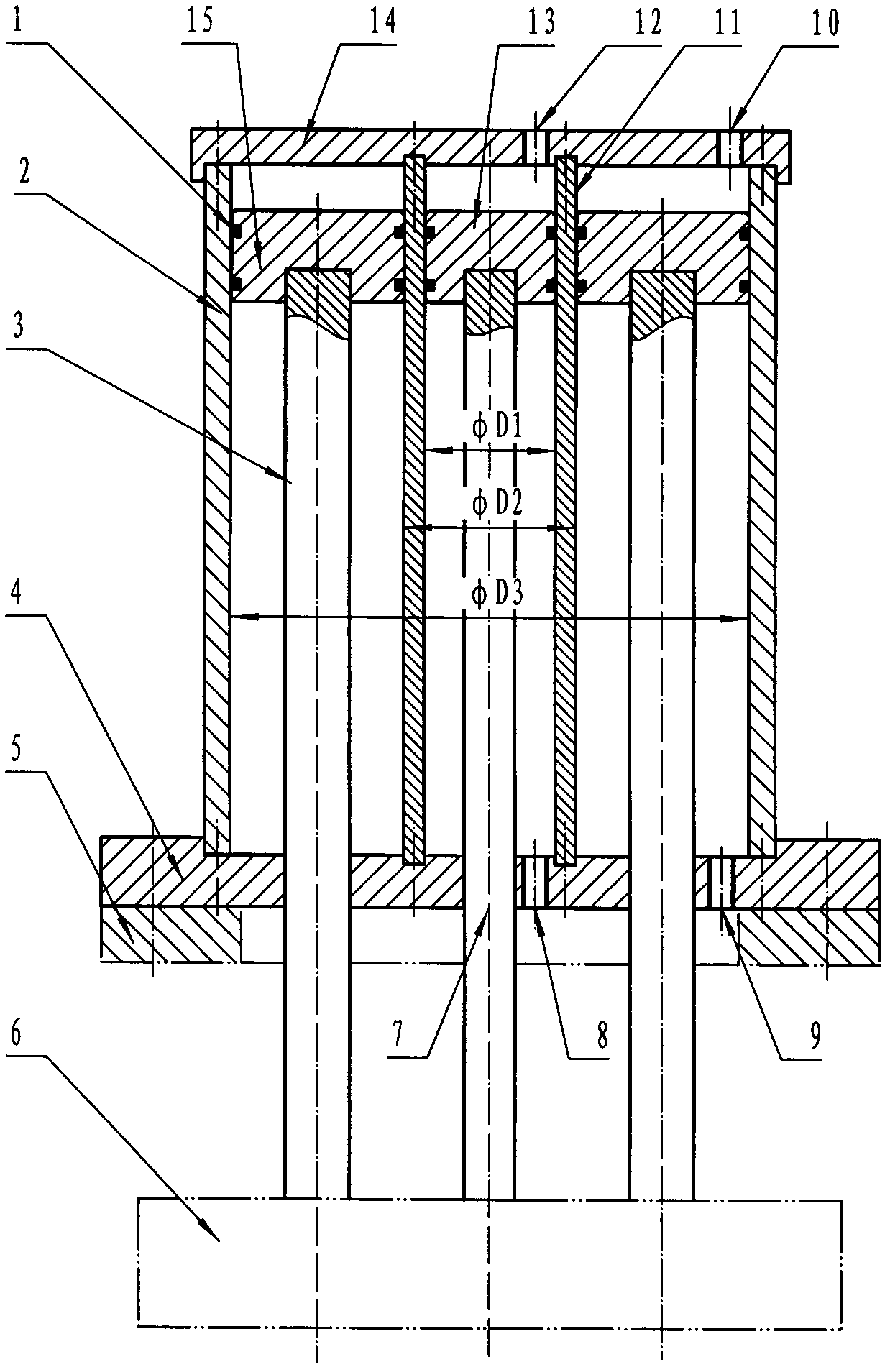
[0012] In Fig. 1, the large oil cylinder passes through the oil cylinder rear cover (14), the large oil cylinder body (2), the oil cylinder front cover (4), 4 large oil piston rods (3) evenly distributed on the circumference and an outer diameter D3, The annular piston (15) of inner hole D2 is formed; The small oil cylinder passes through the oil cylinder rear cover (14), the small oil cylinder body (11), the oil cylinder front cover (4), the small oil piston rod (7) and an outer diameter D1 Piston (15) forms. The large oil cylinder and the small oil cylinder share the oil cylinder rear cover (14) and the oil cylinder front cover (4). The strokes of the two are exactly the same, and the large oil piston rod (3) and the small oil piston rod (7) act together on the plastic molding machine to close the mold. On the formwork (6), the assembly of large and small oil cylinders is fixed on the oil cylinder installation flange plate (5) through the oil cylinder front cover (4). The o...


PUM


Abstract

The invention relates to a combined energy-saving oil cylinder. Two oil cylinders with different cylinder diameter and identical strokemm are combined into a whole to drive plastic molding mechanical moulds to realize mold clamping. In a rapid mold clamping stage, a hydraulic system only supplies pressure oil to a small oil cylinder, a big oil cylinder absorbs static oil without pressure from an auxiliary oil tank to fill liquid, and he big oil cylinder and the small oil cylinder act synchronously. In a high pressure mold closing stage, the hydraulic system supplies the pressure oil to the big oil cylinder and the small oil cylinder simultaneously through the switch of an electromagnetic reversing valve. Therefore, the combined energy-saving oil cylinder can increase mold clamping speed and provide an extremely large mold closing force only by a small hydraulic system. The oil cylinder motor power and an oil pump flow are reduced greatly; a hydraulic circuit board, hydraulic valves, oil cylinders, oil coolers and size of piplines are decreased at the same time; and the combined energy-saving oil cylinder is low in cost and energy conservation.

Description

Technical field [0001] The invention relates to a mold clamping oil cylinder used on a plastic molding machine, in particular to an energy-saving oil cylinder which can realize rapid high-pressure mold clamping and generate a large mold clamping force by using an oil pump motor with a small power and an oil pump with a small flow rate. Background technique [0002] At present, the hydraulic mold clamping mechanism on the known plastic molding machine uses an oil cylinder to perform direct pressure mold clamping. When molding plastic products with a large surface area, a large clamping force is required, so the diameter of the mold clamping cylinder and the hydraulic pressure The pressure of the system is very high, and to produce a certain mold closing speed, the flow of the oil pump must also be large. The power of the oil pump motor is proportional to the pressure and flow of the hydraulic system, so the power of the oil pump motor must be very large. At the same time, the...

Claims


Application Information

Patent Timeline
Patent Type & Authority Applications(China)
IPC IPC(8): B29C33/20
Inventor 何德方邓少东
Owner ZHANGJIAGANG BEIER MACHINERY
Why Eureka
Try Eureka