Eureka AIR delivers breakthrough ideas for toughest innovation challenges, trusted by R&D personnel around the world.

Intelligent protection net

A protective net and intelligent technology, applied in the field of transportation technology and civil engineering, geotechnical engineering, can solve the problems that the force value sensing device is susceptible to electromagnetic interference, cannot adapt to field environmental conditions, and the monitoring equipment is expensive, etc., achieving good application prospects, The effect of flexible use and high practical value

Inactive Publication Date: 2013-06-05
XIAN JINHE OPTICAL TECH
View PDF1 Cites 9 Cited by
  • Summary
  • Abstract
  • Description
  • Claims
  • Application Information

AI Technical Summary

Problems solved by technology

[0003] Traditional force sensing devices are susceptible to electromagnetic interference, have a short service life, high failure rate, and poor stability, and cannot adapt to field environmental conditions
Chinese Patent Application No. 201120126098.7 "Fiber Bragg Grating Tensile Sensing Device for Rolling Stone Flexible Protection Net" discloses a scheme, which uses a fiber grating-based sensing technology, which has the advantages of anti-electromagnetic interference, etc., but its monitoring equipment is expensive, resulting in The high cost limits its scope of use in actual engineering

Method used


Image

  • Intelligent protection net
  • Intelligent protection net
  • Intelligent protection net

Examples


Embodiment 1

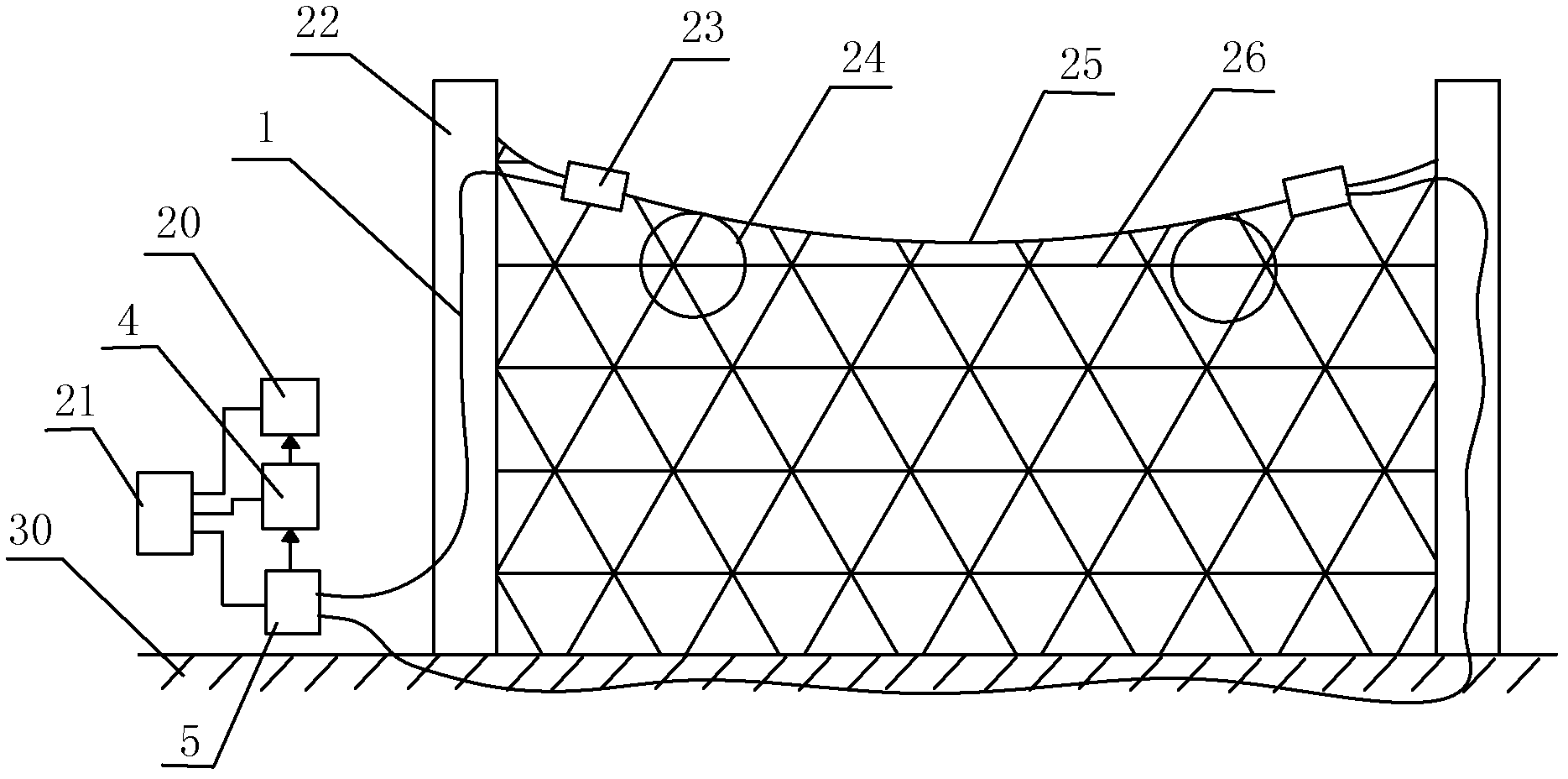
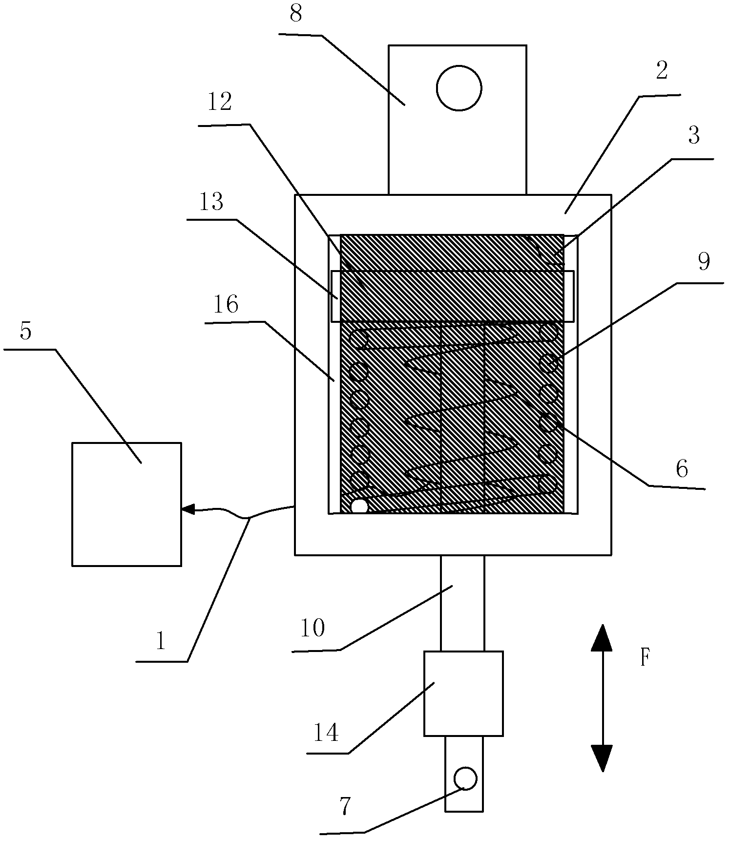
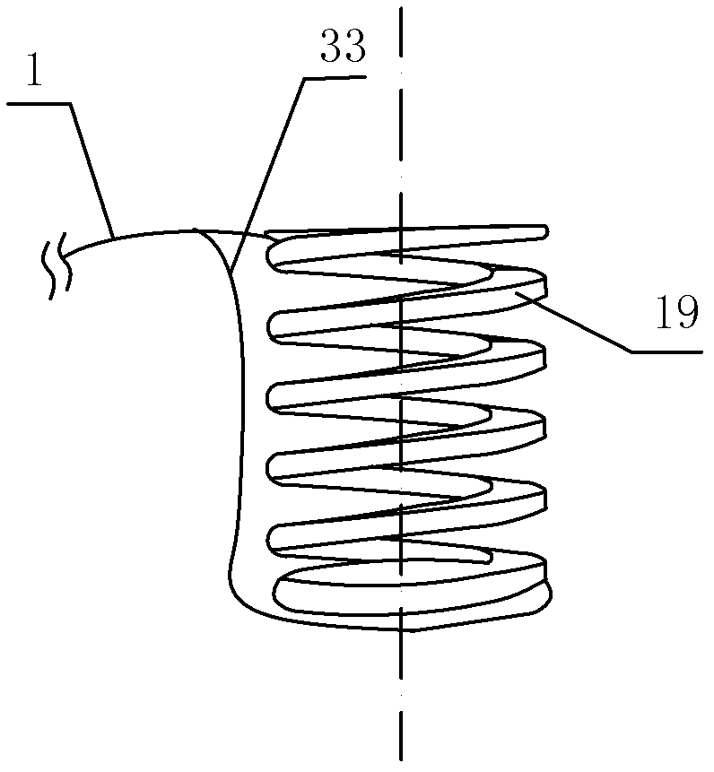
[0039] like figure 1 , 2 , a kind of intelligent protective net shown in 3, 4, comprises the column 22 that is fixed on the ground 30 and the protective net 26 that is installed between the column 22, and the top of described protective net 26 is provided with dragline 25, and described drag An optical fiber sensing device 23 is installed on the cable 25, and the optical fiber sensing device 23 includes a housing 2, an optical fiber bending sensing unit 6 and a top cover 3 arranged on the housing 2, and the housing 2 is provided with an opening And the moving bar 10 that is slidingly matched with the opening, one end of the moving bar 10 is connected with the slide plate 12 located in the housing 2, and the other end of the moving bar 10 is located outside the housing 2; A pull ring 8, the moving rod 10 is provided with a pull eye 7, the pull ring 8 and the pull eye 7 are connected to a pull cable 25, and the pull cable 25 is connected to a column 22; the optical fiber bendin...

Embodiment 2

[0050] like Figure 5 As shown, the difference between this embodiment and Embodiment 1 is that the curved support is a spring 38, and a plurality of deformed teeth 4-1 and a plurality of deformed teeth 2 4-2 are correspondingly arranged in two adjacent turns in the spring 38 Between the spring wires, the first deformed tooth 4-1 and the second deformed tooth 4-2 are alternately arranged. In this embodiment, the structures, connections and working principles of other parts are the same as those in Embodiment 1.

Embodiment 3

[0052] like Figure 6 and 7 As shown, the difference between this embodiment and Embodiment 1 is that the curved bracket is a corrugated tube 40, and the first deformed tooth 4-1 and the second deformed tooth 4-2 are arranged on the wall 42 of the corrugated tube 40 to be concave. On the opposite two sides of the place, and the first deformed tooth 4-1 and the second deformed tooth 4-2 are arranged alternately. In this embodiment, the structures, connections and working principles of other parts are the same as those in Embodiment 1.


PUM


Abstract

The invention discloses an intelligent protection net which comprises upright columns and a protection net body arranged in the upright columns. A pull cable is arranged at the top end of the protection net body. Optical fiber sensing devices are arranged between the pull cable and the upright columns. Each fiber sensing device comprises a shell body and an optical fiber bending sensing unit. The shell body is provided with an opening. One end of a moving rod is connected with a slide plate located inside the shell body. Connection devices are arranged on the shell bodies and moving rods located outside the shell bodies and are respectively connected with the upright columns and the pull cable. Each optical fiber bending sensing unit comprises a curve support, a plurality of first deformation teeth and a plurality of second deformation teeth, wherein the plurality of first deformation teeth and the plurality of second deformation teeth are consecutively distributed on the curve support, and a signal optical fiber is clamped between deformation teeth on two sides. An auxiliary spring in parallel connection with each curve support is arranged between each slide plate and the inner wall of each shell body. The signal optical fiber is connected with a testing unit through an optical cable. The testing unit is connected with a processing unit which is connected with a communication alarm unit. The intelligent protection net has the advantages of being high in precision, resistant to electromagnetism interference, and low in cost, and is suitable for actual project environments.

Description

technical field [0001] The invention belongs to the technical fields of traffic technology and civil and geotechnical engineering, and in particular relates to an intelligent protective net based on optical fiber sensing technology. Background technique [0002] The monitoring and forecasting of geological disasters along railways and highways is the basis for ensuring the normal operation of traffic. Due to my country's vast territory and complex geological conditions, landslides, collapses, and rolling rocks are the main forms of geological disasters, which seriously affect the safety of vehicles. In the protection of dangerous rocks and rolling stones, the application of flexible protective nets is becoming more and more extensive. However, the flexible passive protective net is not very safe. When the falling energy of the rolling stone exceeds the bearing capacity of the protective net, the rolling stone will break through the protective net and enter the railway or roa...

Claims


Application Information

Patent Timeline
Patent Type & Authority Applications(China)
IPC IPC(8): E01F7/04G01L1/24
Inventor 杜兵
Owner XIAN JINHE OPTICAL TECH
Why Eureka
Eureka Blog
Learn More