Boiler system with U-shaped flue and boiler water charging system

A flue, U-shaped technology, applied in the boiler system and boiler water supply system, can solve the problems of condensate recovery, flue corrosion, insufficient heat exchange, etc., and achieve the effects of reducing emissions, saving water resources, and reducing concentrations

Active Publication Date: 2013-06-05
京能科技(易县)有限公司
View PDF14 Cites 13 Cited by
  • Summary
  • Abstract
  • Description
  • Claims
  • Application Information

AI Technical Summary

Problems solved by technology

[0007] The invention provides a boiler system with a U-shaped flue and a boiler water replenishment system to solve problems such as insufficient heat exchange, flue corrosion, and condensed water recovery caused by the fast smoke velocity, which is beneficial to the depth of the flue gas. waste heat recovery

Method used


Image

  • Boiler system with U-shaped flue and boiler water charging system
  • Boiler system with U-shaped flue and boiler water charging system
  • Boiler system with U-shaped flue and boiler water charging system

Examples


Embodiment 1

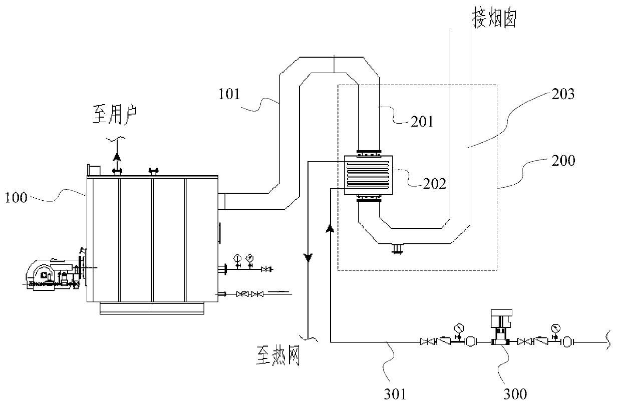
[0029] Such as figure 2 As shown, the boiler system with a U-shaped flue in this embodiment includes: a boiler body 100, a boiler flue 101 and a U-shaped flue device 200, and the U-shaped flue device 200 is connected to the boiler body 100 through the boiler flue 101. connect.

[0030] The U-shaped flue device 200 includes: a front vertical flue 201, which is airtightly connected with the boiler flue, and is used to make the flue gas discharged from the boiler flow from top to bottom in the front vertical flue; a heat exchanger 202, which is vertically connected to the front end. The straight flue 201 is airtightly connected, and is used to make the smoke discharged from the front vertical flue 201 flow through the water pipe of the heat exchanger 202 from top to bottom; the rear end "J" shaped flue 203 is airtightly connected with the heat exchanger 202, The smoke exhausted by the heat exchanger 202 flows from bottom to top in the rear end "J" shaped flue 203 and is dischar...

Embodiment 2

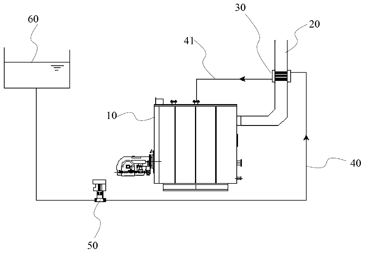
[0034] Such as Figure 4 As shown, the boiler system with a U-shaped flue in this embodiment includes: a boiler body 100, a boiler flue 101, a U-shaped flue device 200, and a condensate tank 210. The U-shaped flue device 200 passes through the boiler flue 101 and The boiler body 100 is connected.

[0035] The U-shaped flue device 200 includes: a front vertical flue 201, which is airtightly connected with the boiler flue, and is used to make the flue gas discharged from the boiler flow from top to bottom in the front vertical flue; a heat exchanger 202, which is vertically connected to the front end. The straight flue 201 is airtightly connected, and is used to make the smoke discharged from the front vertical flue 201 flow through the water pipe of the heat exchanger 202 from top to bottom; the rear end "J" shaped flue 203 is airtightly connected with the heat exchanger 202, The smoke exhausted by the heat exchanger 202 flows from bottom to top in the rear end "J" shaped flue...

Embodiment 3

[0046] The U-shaped flue boiler of this invention can not only be directly connected to the heat exchanger to recover primary waste heat, but also can be connected to a heat pump to perform deep flue gas waste heat recovery.

[0047] Take the winter heating of a residential area as an example: the boiler provides heating and water supply for users, and the heat pump system is connected to the boiler heat exchanger to heat the return water for secondary heating.

[0048] Such as Figure 5 As shown, the boiler system with U-shaped flue for district heating includes: boiler body, boiler flue and U-shaped flue device, condensate tank and heat pump, and the U-shaped flue device passes through the boiler flue and the boiler body The U-shaped flue device includes: the front-end vertical flue, which is airtightly connected with the boiler flue, and is used to make the flue gas discharged from the boiler flow from top to bottom in the front-end vertical flue; the heat exchanger, and T...


PUM


Abstract

The invention discloses a boiler system with a U-shaped flue and a boiler water charging system. The boiler system comprises a boiler body, a boiler flue and a U-shaped flue device, wherein the U-shaped flue device is connected to the boiler body through the boiler flue, the U-shaped flue device comprises a front end vertical flue, a heat exchanger and a rear end J-shaped flue, the front end vertical flue is connected to the boiler flue in a sealing mode, the fume which is discharged by a boiler flows from top to bottom in the front end vertical flue, the heat exchanger is connected to the front end vertical flue in a sealing mode, the fume which is discharged by the front end vertical flue flows the water pipe of the heat exchanger from top to bottom, the rear end J-shaped flue is connected to the heat exchanger in a sealing mode, the fume discharged by the heat exchanger flows from bottom to top in the rear end J-shaped flue and is discharged, and the rear end J-shaped flue, the front end vertical flue and the heat exchanger are connected to form a U shape. The problems that the heat exchanging is not complete due to quick flue speed, the flue is corroded, and the condensate is recovered are solved. The residual heat of the fume can be recovered deeply.

Description

technical field [0001] The invention relates to the technical field of boilers, in particular to a boiler system with a U-shaped flue and a boiler water supply system. Background technique [0002] Due to the increasing shortage of oil and gas resources and the high cost of fuel, it is increasingly urgent to improve boiler efficiency. Among them, the utilization of boiler exhaust heat is one of the effective ways to improve boiler efficiency. [0003] Such as figure 1 Shown is the boiler system in the prior art, which includes: boiler body 10, horizontal flue 20, vertical flue 21 (tail flue), heat exchanger 30, water supply pipes (40, 41), water pump 50 and Constant pressure water tank 60. The boiler flue connection method is as follows: the heat exchanger 30 (or economizer) is directly installed at the flue gas outlet of the vertical flue 21, and the vertical flue 21 is connected to the main flue gas flue leading to the outside. The flue gas discharged from the boiler bo...

Claims


Application Information

Patent Timeline
Patent Type & Authority Applications(China)
IPC IPC(8): F22D1/02F24H9/00F24D3/18F23J11/00
CPCY02P10/265Y02P10/283Y02P10/25Y02P80/15
Inventor 孙翠霞王力彪贾向东陈鹏马国通刘玉龙刘超陈海文王正兴王涛
Owner 京能科技(易县)有限公司
Why Eureka
Try Eureka