
Power electronic transformer substation

A technology of power electronics and substations, applied in the direction of panel/switching station circuit devices, etc., can solve the problems of large substation area and land acquisition investment, low reliability and operation stability, bulky primary equipment of substations, etc., to simplify the main equipment configuration, improve precise control capability, and improve the effect of safe and stable operation level

Active Publication Date: 2013-06-05
STATE GRID CORP OF CHINA +1
View PDF5 Cites 11 Cited by
  • Summary
  • Abstract
  • Description
  • Claims
  • Application Information

AI Technical Summary

Problems solved by technology

[0004] At present, the main problems faced by conventional substations are: with the continuous improvement of transmission voltage level and system short-circuit capacity, the requirements of function and insulation performance make the primary equipment of substations more and more bulky, the manufacturing difficulty is increased, and the area of ​​substations and investment in land acquisition are increasingly huge.
At the same time, not only industrial and mining enterprises, but also residential users have higher and higher requirements for power supply quality. Traditional substations have limited control capabilities, primary and secondary equipment operation reliability and operational stability are not high, accurate real-time control capabilities are poor, and environmental protection effects Disadvantages such as unsatisfactory are becoming more and more obvious, and it is becoming more and more difficult to solve the short-circuit current problem of the power grid with traditional technology

Method used


Image

  • Power electronic transformer substation
  • Power electronic transformer substation
  • Power electronic transformer substation

Examples


Embodiment Construction

[0018] The present invention will be described in detail below in conjunction with the accompanying drawings and embodiments.

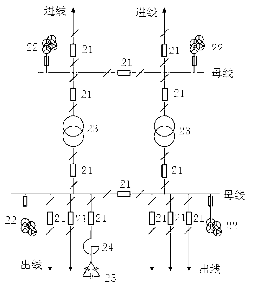
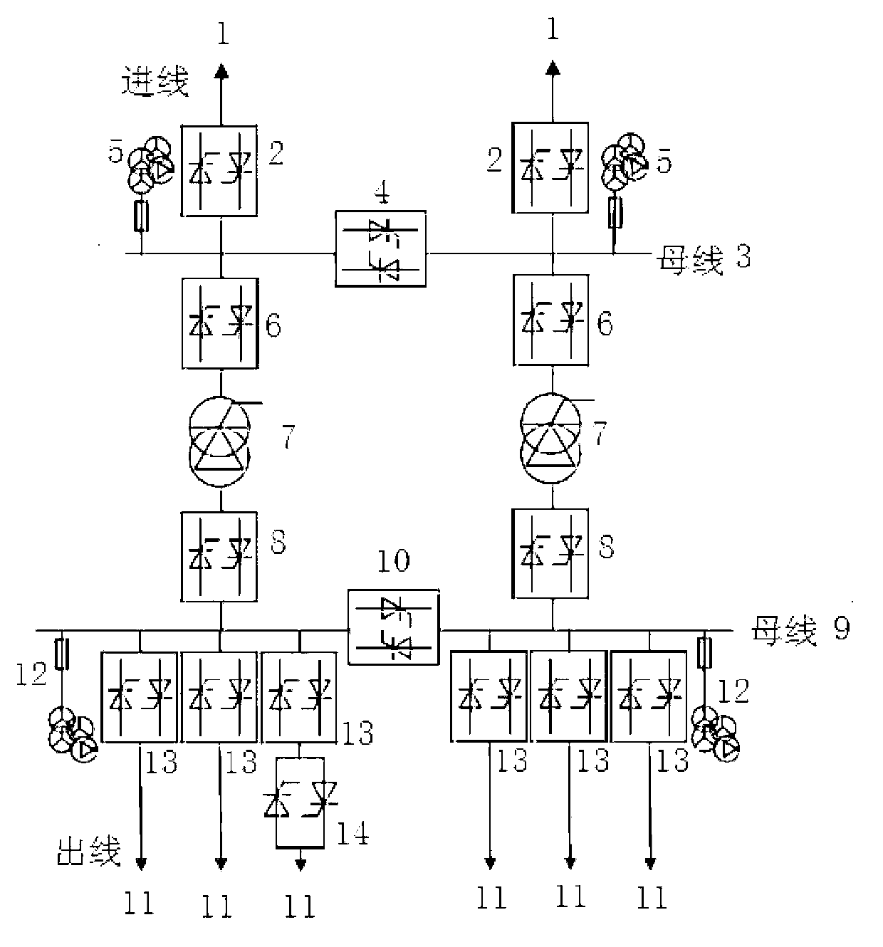
[0019] Generally speaking, electric energy is fed into the substation by the incoming line, distributed through the busbar, switched on and off by the switchgear (including circuit breakers and isolating switches), and transformed by the voltage level of the transformer, and finally sent out through the outgoing line. Such as figure 1 As shown, the conventional substation is designed around traditional primary equipment, such as mechanical-electrical circuit breaker 21, electromagnetic transformer 23, inductive current-limiting reactor 24, voltage transformer 22, and reactive power compensation capacitor 25, etc. However, the present invention mainly adopts power electronic equipment such as solid-state circuit breakers, power electronic transformers, and solid-state current limiters.

[0020] Such as figure 2 As shown, the present invention includ...


PUM


Abstract

The invention relates to a power electronic transformer substation. The power electronic transformer substation comprises a plurality of power inlet wires, each of the power inlet wires is connected with an inlet wire side bus through a first solid state breaker, for each power inlet wire, a voltage transformer is connected on the inlet wire side bus in parallel, a second solid state breaker is arranged on the inlet wire side bus between two inlet wires, each inlet wire is further connected with an outlet wire side bus through a third solid state breaker, a power electronic transformer and a fourth solid state breaker, a fifth solid state breaker is arranged on the outlet wire side bus between two inlet wires, for each inlet wire, the outlet wire side bus leads out three power outlet wires, and a voltage transformer is connected on the outer side of each of the three power outlet wires in parallel, and a sixth solid state breaker is arranged on each power outlet. Except regular functions, the power electronic transformer substation can achieve rapid isolation of failure, improve precise control ability of a power grid, improve safe and stable operation level of the power grid, and meanwhile, change the existing structure form of a transformer substation, reduce the size of a main equipment, simplify the configuration of the main equipment, and greatly reduce occupied space.

Description

technical field [0001] The invention relates to a new type of substation, in particular to a power electronic substation. Background technique [0002] A substation is a power facility in the power system that transforms voltage, receives and distributes electric energy, controls the flow of power, and adjusts voltage. It connects the power grids of all levels of voltage through transformers. In addition to transformers, substation equipment also includes switching equipment for opening and closing circuits, bus bars for collecting current, transformers for measurement and control, instruments, relay protection devices, lightning protection devices, and dispatching communication devices. Usually, substations are also equipped with Reactive power compensation equipment and high impedance equipment, etc. [0003] Conventional substations generally include primary equipment and secondary equipment. In terms of primary equipment, single-phase or three-phase electromagnetic tra...

Claims


Application Information

Patent Timeline
IPC IPC(8): H02B1/24
Inventor 宋璇坤肖智宏李敬如张祥龙
Owner STATE GRID CORP OF CHINA
Learn More