
Anti-clogging capillary drip irrigation emitter with flat plate superimposition structure

A drip irrigator and flat plate technology, applied in the field of anti-clogging capillary drip irrigators, can solve problems such as easy clogging, achieve balanced dripping speed, avoid water evaporation and microbial growth, and reduce the average cost of use and repeated construction costs.

Inactive Publication Date: 2013-06-12
谭朝晖
View PDF3 Cites 11 Cited by
  • Summary
  • Abstract
  • Description
  • Claims
  • Application Information

AI Technical Summary

Problems solved by technology

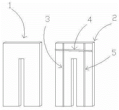
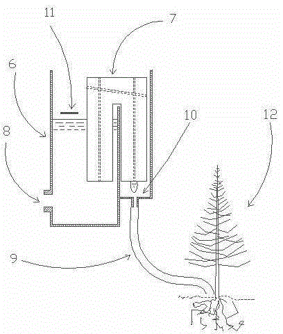
[0016] In order to overcome the defect that the drip irrigation dripper is easy to be blocked, the present invention designs a capillary drip irrigation device, which is characterized in that at least one "n" shaped smooth and hard flat plate material can be used to make fine grinding marks or depressions on the surface of the flat plate , or not, another piece of "n"-shaped smooth and hard flat material, can make fine wear marks or depressions on the surface of the flat plate, or not, stack the flat plates together and clamp them, between the flat materials Form a narrow gap to form a micro-water delivery device, and make the micro-water delivery device straddle the edge of the container. One end of the micro-water delivery device is immersed in the water in the container, and the other end corresponds to the water collection device placed outside the container.

Method used


Image

  • Anti-clogging capillary drip irrigation emitter with flat plate superimposition structure
  • Anti-clogging capillary drip irrigation emitter with flat plate superimposition structure
  • Anti-clogging capillary drip irrigation emitter with flat plate superimposition structure

Examples


Embodiment Construction

[0045] best practice

[0046] Select the float flat glass with standard quality and stable chemical properties to make the micro-water delivery device, and control the thickness and number of capillary marks, running marks and gravity marks in the process of making the micro-water delivery device, and control the dripping speed of the micro-water delivery device It is made into 3-4 drops / minute, and the daily water supply of each drip irrigation port is about 1000ml, which is more suitable for the needs of plant growth, and adopts an uninterrupted drip irrigation system without manual intervention, which saves labor input.

[0047] Beneficial effect

[0048] In the capillary drip irrigation device, since the passage of water from the container to the outside of the container is a narrow gap rather than a micropore, the driving force for water movement is the capillary force of the narrow gap on the water rather than the pressure, and the capillary force only acts on the wate...


PUM


Abstract

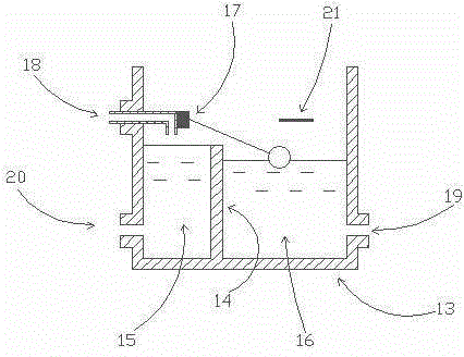
The invention discloses an anti-clogging capillary drip irrigation emitter with a flat plate superimposition structure. On basis of a physical phenomenon that water in a narrow slit rises up under the action of capillary force, at least two n-shaped flat plates are used to form a stable narrow slit to enable water in a container to move upwards and diffuse outside the container along the narrow slit, and then the balance between gravity of water and surface tension of the narrow slit to water is broken, as a result, the required drip irrigation speed is obtained, water is enabled to move from the inside of the container to the outside of the container at a low speed, and water-saving irrigation is performed on a targeted plant. The capillary force only works on water and has no effect on solids such as sandy soil, and meanwhile, the uninterrupted drip irrigation scheme is adopted, so that salt substances are diluted continuously to prevent salt accumulation; and further, a micro water delivery device is placed in a working environment insolated from sunlight, so that microbes are prevented from breeding. In this way, the capillary drip irrigation emitter can be prevented from being clogged by sandy soil, salt and microbes, and meanwhile, a super-large size drip irrigation system free from limitation of pressure attenuation can be constructed by utilizing the theory of communicating vessels.

Description

technical field [0001] The invention relates to a drip irrigation device, in particular to an anti-clogging capillary drip irrigation device with a flat plate superimposed structure, which can realize the function of running water from the inside of the container to the outside of the container at a slow speed to perform water-saving irrigation on target plants. Background technique [0002] In order to meet the needs of production and life in human society, various water conservancy irrigation projects have been invented. However, due to the increasing shortage of water resources, people are forced to adopt more economical irrigation methods. Water-saving irrigation in human society has made a significant contribution. [0003] Drip irrigation is to use a set of special equipment to filter the pressure water (which can be pressurized by the water pump or the pressure generated by the terrain drop), and then pass through the water delivery pipe network at all levels to th...

Claims


Application Information

Patent Timeline
IPC IPC(8): A01G25/00
CPCY02A40/22
Inventor 谭朝晖
Owner 谭朝晖
Learn More