
Fluidic generator

A technology of jet flow generator and high-voltage AC, which is applied in the direction of spraying electric energy devices, chemical instruments and methods, and cleaning methods using gas flow, etc., can solve the problems of non-concentrated air flow energy, secondary pollution of components, and inability to be cleaned. Achieve the effect of concentrated jet energy, small divergence, and simple composition and structure

Inactive Publication Date: 2013-06-12
XIAMEN UNIV
View PDF10 Cites 1 Cited by
  • Summary
  • Abstract
  • Description
  • Claims
  • Application Information

AI Technical Summary

Problems solved by technology

The system design is complicated and the power consumption is high. The main disadvantage is that the energy of the air flow used for cleaning is not concentrated, which consumes a lot of energy, but some local small parts, such as corners or crevices, cannot be cleaned; and the gas comes from the outside air, resulting in The gas jet will inevitably contain pollutant particles, which will cause secondary pollution to components during the cleaning process

Method used


Image

  • Fluidic generator
  • Fluidic generator

Examples


Embodiment 1

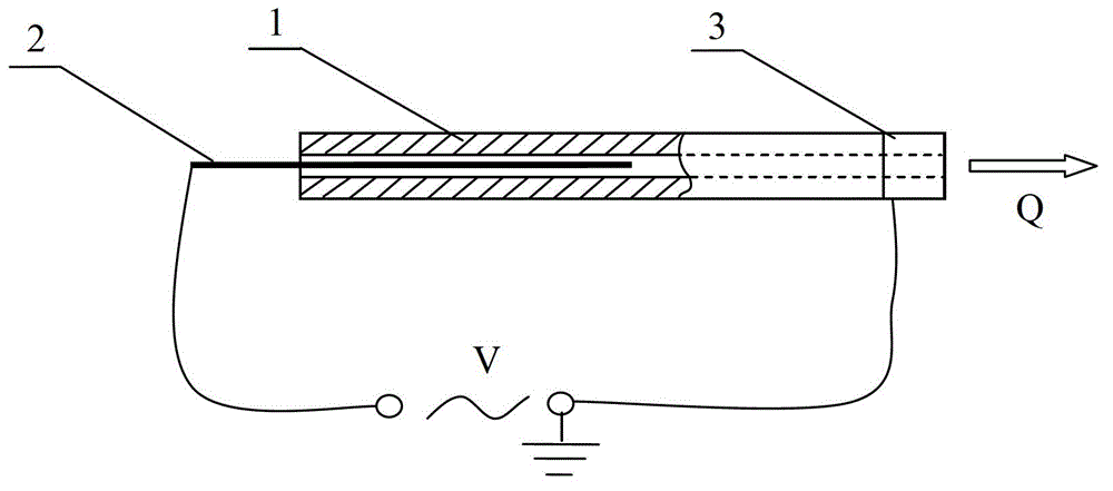
[0021] see figure 1 , The present invention is equipped with a round tube 1 (insulating dielectric tube), a needle electrode 2, a ring electrode 3 (a strip-shaped copper foil ring electrode) and a high-voltage AC power supply. The material of the circular tube 1 is quartz glass. The circular tube 1 has an inner diameter of 1 mm, a tube wall thickness of 1 mm, and a length of 30 mm. The needle electrode 2 is inserted from the rear end of one end 1 of the round tube, and the ring electrode 3 is wound on the outer wall of the front end of the round tube 1 . The needle electrode 2 is a copper wire needle electrode made of copper wire with a diameter of 0.3 mm. The ring electrode 3 is a strip-shaped copper foil ring electrode made of copper foil with a thickness of 0.02 mm and a width of 5 mm. The axial distance between the needle electrode 2 and the ring electrode 3 is 10mm, and the needle electrode 2 and the ring electrode 3 are respectively electrically connected to two outpu...

Embodiment 2

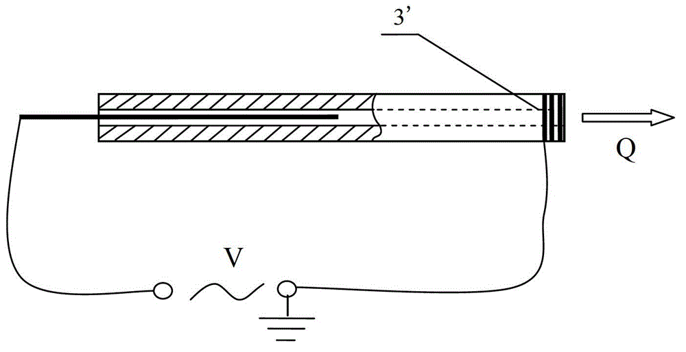
[0026] see figure 2 , similar to Embodiment 1, the only difference is that the ring electrode 3' is made of 3 turns of copper wire with a diameter of 0.3 mm to bind the ring electrode.


PUM

PropertyMeasurementUnit
The inside diameter ofaaaaaaaaaa
Tube wall thicknessaaaaaaaaaa
Lengthaaaaaaaaaa

Abstract

The invention relates to a fluidic generator, and provides the fluidic generator with light weight, small size, simple structure and convenience for operation and control. An insulating dielectric tube, a pin electrode, a ring electrode and a high voltage alternating current power source are arranged; a central through hole is arranged in the insulating dielectric tube; the pin electrode is inserted in the central through hole of the insulating dielectric tube; the ring electrode is wound on the outer wall of the front end of the insulating dielectric tube; axial space is reserved between the pin electrode and the ring electrode; and the pin electrode and the ring electrode are electrically connected with two output ends of the high voltage alternating current power source respectively. A jet flow is generated by virtue of atmosphere alternating discharge, and the addition of an air source as well as the configuration of air source equipment such as an air compressor or an air blower and a filter unit can be avoided. During use, the fluidic generator is mounted near a position requiring jet flow or is held by a hand, with the outlet jet flow aiming at the required local position for jetting.

Description

technical field [0001] The invention relates to a jet generator. In particular, it relates to a jet generator for generating jets by atmospheric pressure AC discharge. Background technique [0002] The high-speed gas jet can quickly clean and remove dust from the surface of the object. For example, after the electronic components are packaged, they are usually arranged in trays to facilitate future transportation and assembly. However, the polluting dust particles in the air will adhere to the components in the tray during storage and transportation, resulting in deterioration of the operating characteristics of electronic components, and even damage to the components. Therefore, the components must be cleaned before assembly to ensure assembly subsequent product quality. [0003] At present, many cleaning methods still use air compressors to generate high-pressure gas jets for cleaning. For this purpose, air compressors or blowers, control systems, filtering devices, con...

Claims


Application Information

Patent Timeline
IPC IPC(8): B05B5/053B08B5/02
Inventor 林麒刘汝兵牛中国杨欢王萌萌
Owner XIAMEN UNIV
Learn More