


Quick Research
Generate reliable direction feasibility study reports for your R&D in just a few steps.

Technical Q&A
Discover and master advanced knowledge NOW. Basics, ideas, possibilities, all at once.

Find Solutions
As an expert in R&D theories, this can generate solutions to your technical problems instantly.

Evaluate Feasibility
Analyze your overall solution with one click, know your potential R&D risks in advance.

Monitor Landscape
Get weekly tech updates, stay abreast of the latest tech innovations and key insights.
Waste heat utilization internal combustion heat engine
An internal combustion hot gas and waste heat technology, applied in the field of thermal energy and power, can solve the problems of affecting efficiency and power density, temperature rise, difficult to reach higher, etc., to achieve the effect of improving efficiency, broad application prospects and high heating efficiency
- Summary
- Abstract
- Description
- Claims
- Application Information
AI Technical Summary
Problems solved by technology
Method used
Image

Examples
Embodiment 1
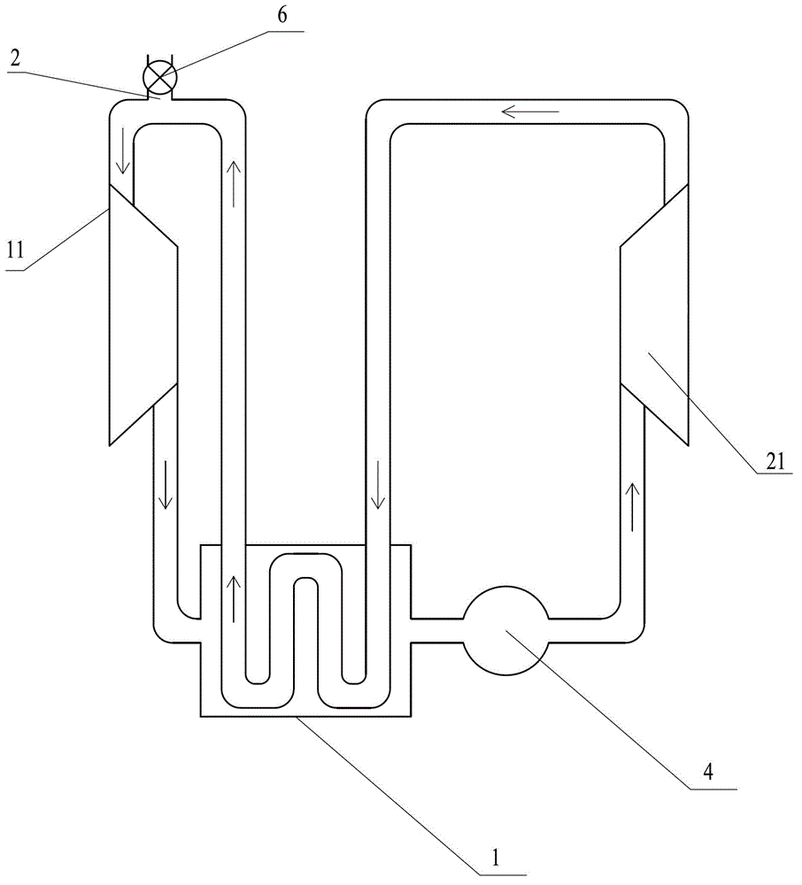
[0030] Such as figure 1 The shown waste heat utilization internal combustion heat engine includes an impeller compressor 11, a turbine 21, an internal combustion combustion chamber 4 and a heat exchanger 1, and the working medium outlet of the impeller compressor 11 is connected to the heated fluid inlet of the heat exchanger 1 The heated fluid outlet of the heat exchanger 1 communicates with the working medium inlet of the turbine 21 through the internal combustion chamber 4, and the working medium outlet of the turbine 21 passes through the cooled fluid of the heat exchanger 1 The channel communicates with the working medium inlet of the impeller compressor 11, and a working medium outlet 2 is provided on the communication channel between the cooled fluid outlet of the heat exchanger 1 and the working medium inlet of the impeller compressor 11, The working medium outlet 2 communicates with the outside world through the control valve 6, and the impeller compressor 11, the tu...
Embodiment 2
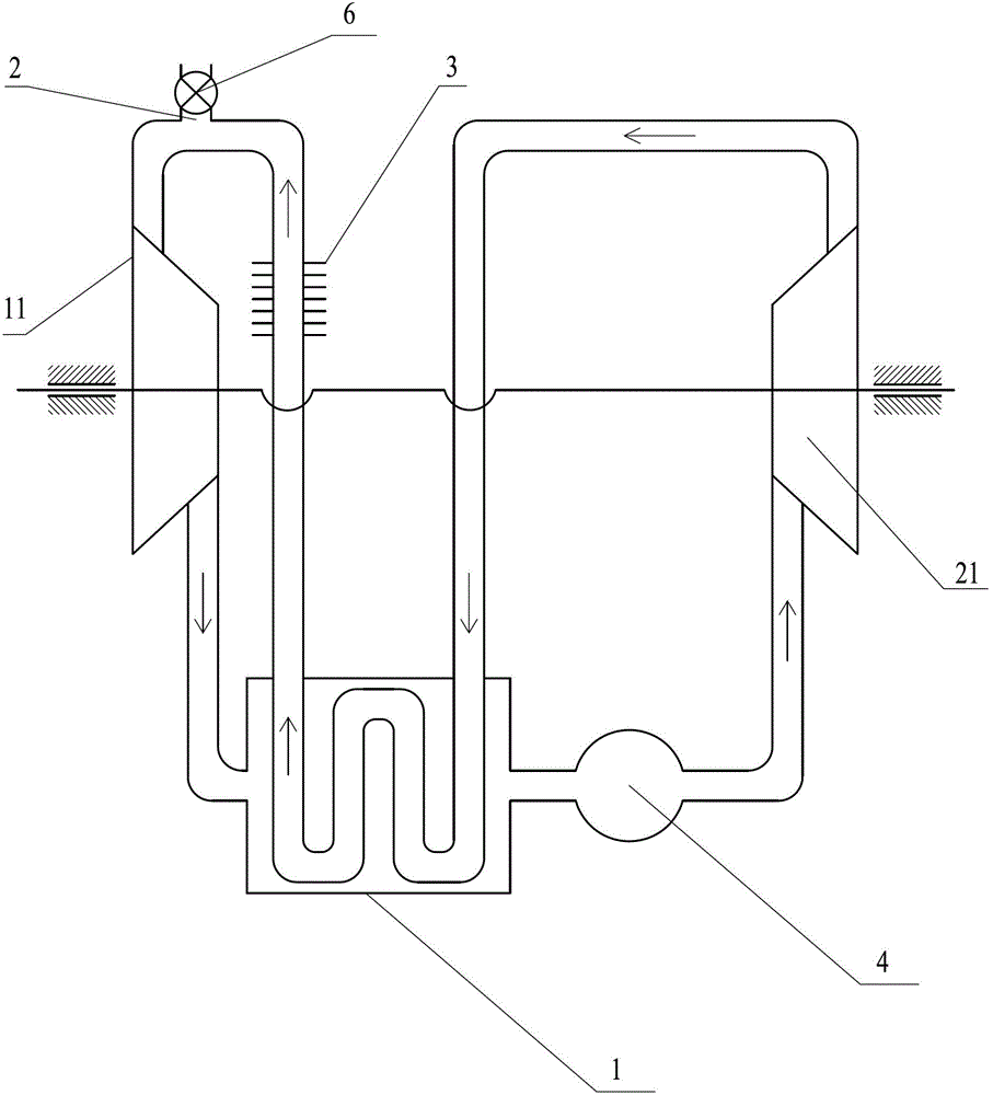
[0035] Such as figure 2 The difference between the waste heat utilization internal combustion air heater shown in Example 1 is that the waste heat utilization internal combustion air heat engine also includes a desuperheater 3, and the desuperheater 3 is arranged at the outlet of the cooled fluid of the heat exchanger 1 and The impeller compressor 11 and the turbine 21 are arranged coaxially on the communication channel between the working medium outlets 2 . The pressure bearing capacity of the closed circulation loop of the working fluid is greater than 5.5MPa.
[0036] As a changeable embodiment, in the structure of the desuperheater 3, the impeller compressor 11 and the turbine 21 do not have to be coaxial. Similarly, the impeller compressor 11 and the turbine 21 are coaxially arranged. In the structure, the desuperheater 3 may not be provided.
Embodiment 3
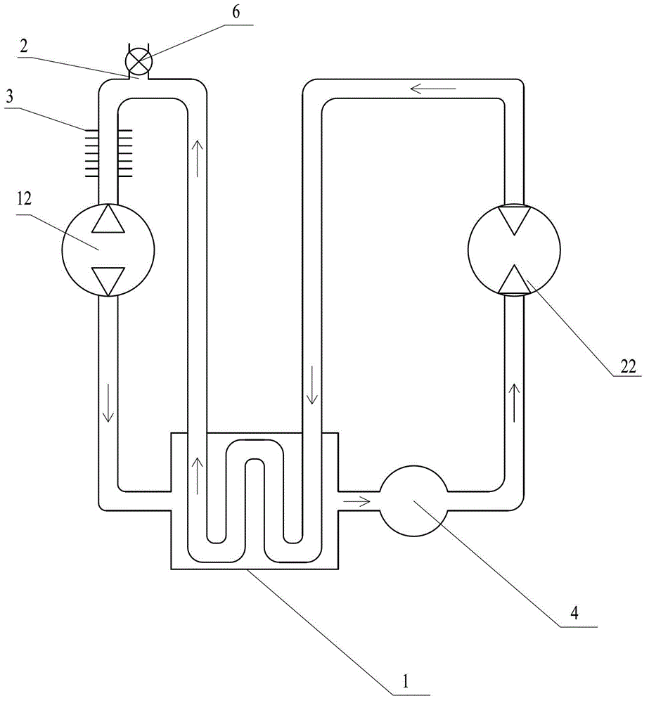
[0038] Such as image 3The shown waste heat utilizes an internal combustion air heater, and its difference from Embodiment 1 is that the compression mechanism is set as a Roots blower 12, the work mechanism is set as a Roots motor 22, and the cooler 3 is arranged on the working surface. On the communication passage between the substance outlet 2 and the working fluid inlet of the Roots blower 12 .
[0039] During specific implementation, optionally, the compression mechanism can also be set as a piston-type compression mechanism, and the described work mechanism can also be set as a piston-type work mechanism, and the piston-type compression mechanism and the piston-type work mechanism are V-shaped It is provided that the waste heat utilization internal combustion heat engine is an α-type or β-type heat engine structure, and the pressure bearing capacity of the closed circulation loop of the working medium is greater than 9.5 MPa.
[0040] All the embodiments of the present i...
PUM
| Property | Measurement | Unit |
|---|---|---|
| Pressure endurance | aaaaa | aaaaa |
| Pressure endurance | aaaaa | aaaaa |
Abstract
Description
Claims
Application Information
 - R&D Engineer
- R&D Manager
- IP Professional
- Industry Leading Data Capabilities
- Powerful AI technology
- Patent DNA Extraction
Browse by: Latest US Patents, China's latest patents, Technical Efficacy Thesaurus, Application Domain, Technology Topic, Popular Technical Reports.
© 2024 PatSnap. All rights reserved.Legal|Privacy policy|Modern Slavery Act Transparency Statement|Sitemap|About US| Contact US: help@patsnap.com