
Oil supply for linear compressors

A technology of linear compressors and oil supply devices, which is applied to mechanical equipment, machines/engines, and liquid displacement machinery, etc. It can solve problems such as difficulty, lower production efficiency, and limit lubricating oil suction and discharge, and achieve simplification The effect of processing technology, improving production efficiency, and large elastic range

Active Publication Date: 2015-09-16
TECHNICAL INST OF PHYSICS & CHEMISTRY - CHINESE ACAD OF SCI
View PDF6 Cites 0 Cited by
  • Summary
  • Abstract
  • Description
  • Claims
  • Application Information

AI Technical Summary

Problems solved by technology

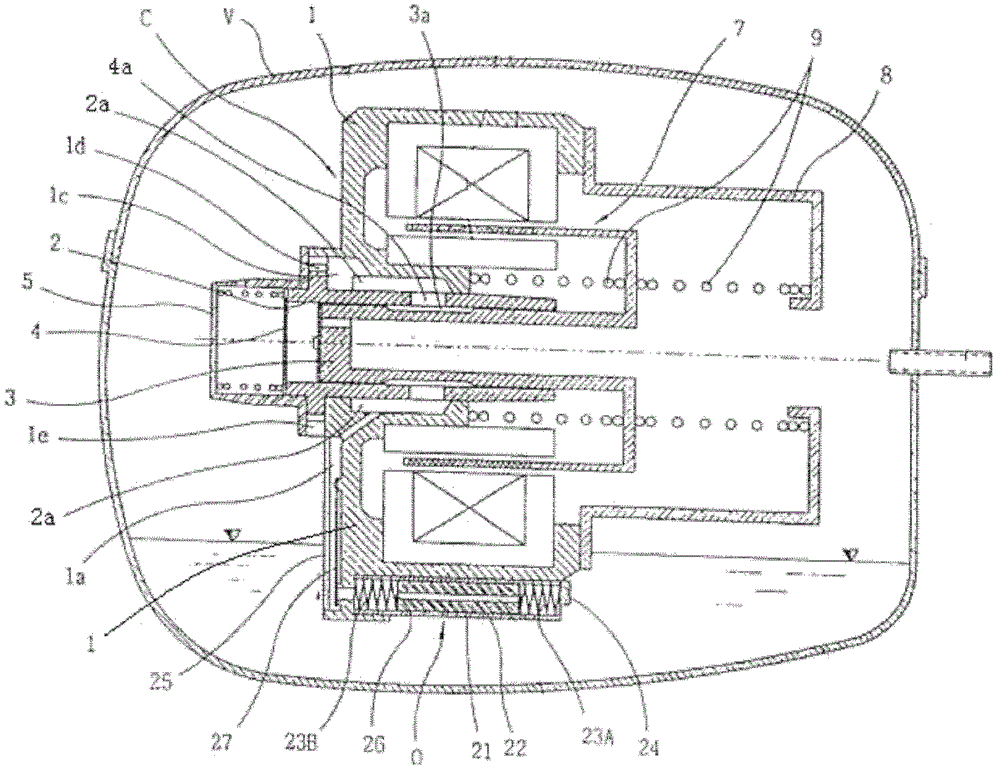
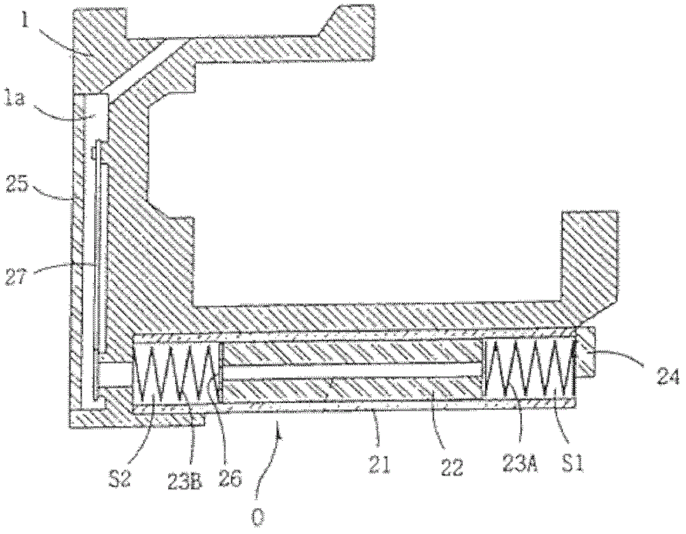
[0010] At present, since the oil suction valve for controlling the oil in and out of the oil supply device of the existing linear compressor is installed in an oil cylinder with a smaller diameter, a smaller oil suction valve is required to meet the installation requirements, and the oil suction valve installed in the oil cylinder has Certain shape, small volume oil suction valve is more difficult to manufacture and assemble
In addition, because the oil suction cap must be inserted into the end of the elastic member with a relatively large pressure, so that the piston located in the middle of the elastic member has a large enough stretching force, but this assembly method is relatively difficult, which limits the stretching force of the piston, thus Limits the suction and discharge of lubricating oil, reducing production efficiency

Method used


Image

  • Oil supply for linear compressors
  • Oil supply for linear compressors
  • Oil supply for linear compressors

Examples


Embodiment Construction

[0031] The specific implementation manners of the present invention will be further described in detail below in conjunction with the accompanying drawings and embodiments. The following examples are used to illustrate the present invention, but are not intended to limit the scope of the present invention.

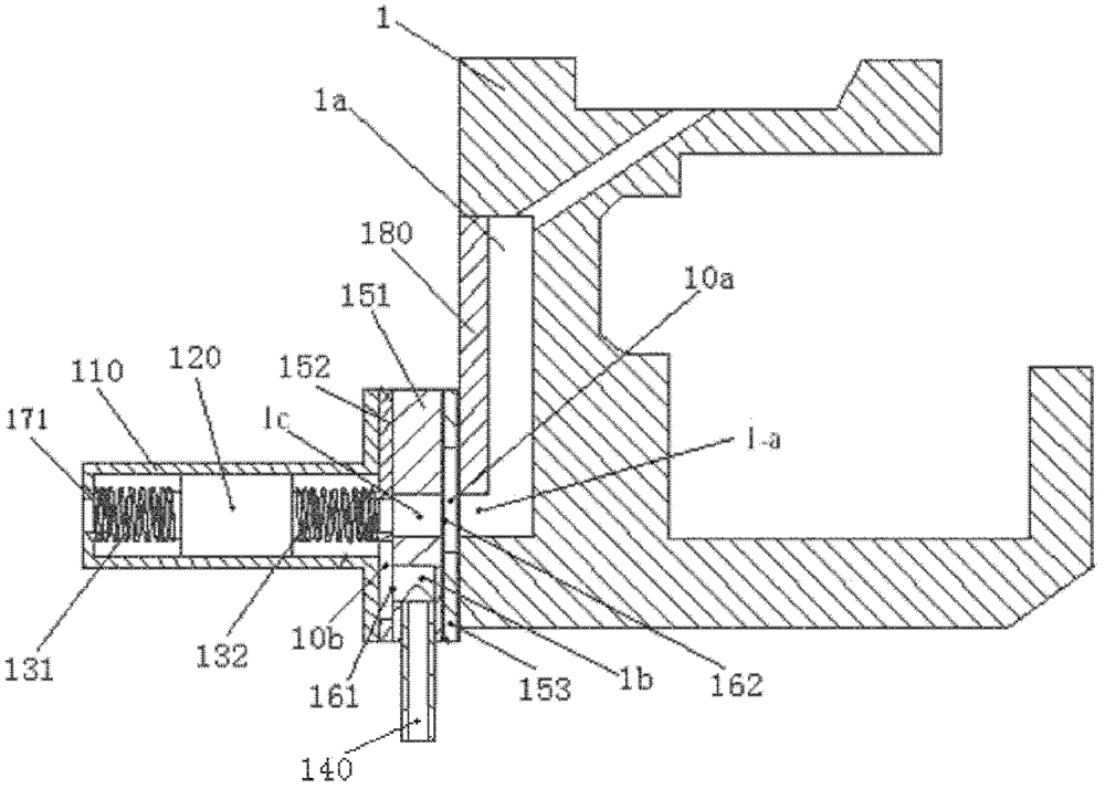
[0032] Such as image 3, an oil supply device for a linear compressor, installed at the bottom of the frame 1 of the linear compressor in a sealed container, the oil supply device includes an oil cylinder 110, a piston 120, an oil suction valve 161, an oil discharge valve 162 and a baffle 151; The frame 1 is provided with an oil discharge channel 1a, one end of the oil discharge channel 1a is connected to the oil tank 2a of the frame 1, and the other end is an oil inlet hole 1-a arranged on the side of the frame 1, and the oil inlet hole 1-a A baffle 151 and an oil cylinder 110 are installed horizontally in sequence, and the baffle 151 has an oil channel 1c connected with...


PUM


Abstract

The invention belongs to the technical field of a linear compressor, in particular to a device for supplying oil for a friction part between a cylinder and a piston in the linear compressor. The oil supply device is arranged at the bottom of a stand of the linear compressor in a closed container; the stand is internally provided with an oil discharge channel; an oil inlet hole of the oil discharge channel is sequentially provided with a baffle and an oil cylinder in a horizontal way; a first spring and a second spring which are deformed by pre-pressing are respectively arranged at the two ends of the piston arranged in the oil cylinder; the bottom of the baffle is provided with an oil inlet channel connected with the oil cylinder; an oil absorption valve is arranged at the part where the oil inlet channel is connected with the oil cylinder; and an oil drain valve is arranged at the part where an oil channel of the baffle is connected with the oil discharge channel. The oil absorption valve is arranged at the wider part where the oil inlet channel is connected with the oil cylinder, and the oil drain valve is arranged at the wider part where the oil channel of the baffle is connected with the oil discharge channel, so that the oil absorption valve and the oil drain valve which are installed in this way are simple in structure and easy to manufacture and assemble, and the processing technology of the oil absorption valve and the oil drain valve can be simplified.

Description

technical field [0001] The invention belongs to the technical field of linear compressors, in particular to a device for supplying oil to friction parts of a cylinder and a piston in a linear compressor. Background technique [0002] The compressor used in traditional refrigeration equipment uses a rotating motor, plus a set of crankshaft and connecting rod transmission mechanism that converts the rotating motion into reciprocating motion to push the piston to compress the refrigerant gas. Since the manufacturing of each component is complicated and friction will be generated between the components, the efficiency of the compressor is reduced and the power consumption is large. [0003] Linear compressors use permanent magnets and coils to form a linear motor instead of a crank mechanism and a rotary motor to make the piston reciprocate to compress the refrigerant. Linear compressors reduce friction between components by reducing the number of transmission components. In o...

Claims


Application Information

Patent Timeline
Patent Type & Authority Patents(China)
IPC IPC(8): F04B39/02
Inventor 田长青彭国宏张立钦唐明生邹慧明
Owner TECHNICAL INST OF PHYSICS & CHEMISTRY - CHINESE ACAD OF SCI
Learn More