
Lithium sulphur battery

A lithium-sulfur battery and electrolyte technology, which is applied in lithium batteries, battery electrodes, non-aqueous electrolyte batteries, etc., can solve the problems of reduced electric charge density, active material mass loss, electric capacity decrease, etc., to improve cycle life and power density, Improved ionic conductivity and improved stability

Active Publication Date: 2013-06-12
POSITEC POWER TOOLS (SUZHOU) CO LTD
View PDF6 Cites 12 Cited by
  • Summary
  • Abstract
  • Description
  • Claims
  • Application Information

AI Technical Summary

Problems solved by technology

[0007] Second, the anions of polysulfide intermediates formed during charge and discharge are highly soluble in polar organic solvents, and these anions can permeate through the separator to reach the anode and produce precipitates at the anode (Li 2 S 2 and Li 2 S), in the process of repeated charging and discharging of the battery, it leads to a decrease in the capacity of the battery
During the discharge process, the expansion and accumulation of solid precipitates on the surface of the cathode can also lead to irreversible electrochemical reactions, which in turn lead to mass loss of active materials.
[0008] Third, in the process of cyclic charging and discharging, dendrites will gradually grow on the lithium electrode, and the dendrites will continue to grow and extend, and finally pass through the electrolyte to reach the cathode, which may cause an internal short circuit of the battery, which is very dangerous. Therefore, the cycle charge and discharge life of this battery is only a few times.
Although some organosulfur polymers, such as DMcT (2,5-dimercapto-1,3,4-thiadiazide), showed relatively good performances in power density and cycle life, their charge density decrease was particularly pronounced, Almost less than 40% of the theoretical charge, even at relatively high temperatures
Although existing reports have shown that carbon-sulfur composites or conductive polymer-sulfur composites have not greatly improved the available power and cycle life

Method used


Image

  • Lithium sulphur battery
  • Lithium sulphur battery
  • Lithium sulphur battery

Examples


Embodiment Construction

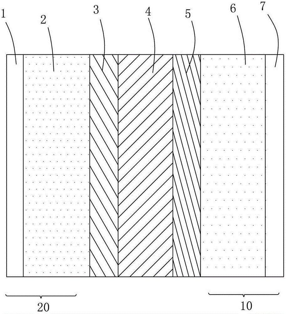
[0037] See attached figure 1 , the present invention provides a lithium-sulfur battery with high energy density and high cycle life. A lithium-sulfur battery includes a positive electrode, a negative electrode, a separator separating the positive and negative electrodes, and an electrolyte therein.

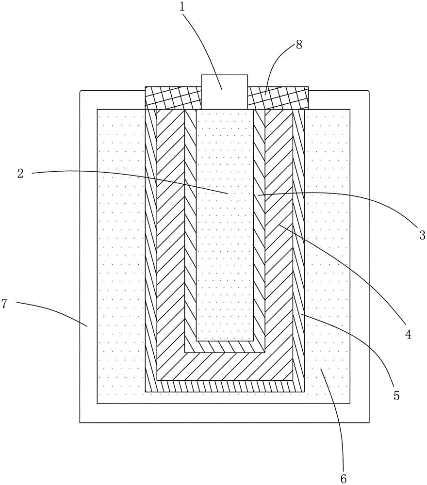
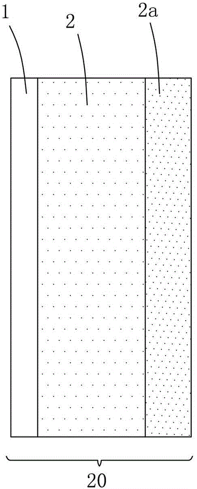
[0038] In this embodiment, the positive electrode of the lithium-sulfur battery, that is, the cathode 10 includes a cathode current collector 7 and a cathode active material 6 . The negative electrode of the lithium-sulfur battery, namely the anode 20 , includes an anode current collector 1 and an anode active material 2 . It can be seen from the drawings that a diaphragm 4 is provided between the cathode active material 6 and the anode active material 2 , and the anode electrolyte 3 and the cathode electrolyte 5 are separated by the diaphragm 4 . Thus, ions generated during charging and discharging of the battery can be transferred through the separator 4 , and the electrolyte ...


PUM


Abstract

The invention relates to a lithium sulphur battery which comprises an anode, an cathode, an electrolyte and a membrane, wherein the anode comprises anode active materials selected from lithium metal, lithium alloys and lithium carbons and an anode current collector, the cathode comprises cathode active materials and a cathode current collector, the cathode active materials comprise at least one kind of sulfur compound selected from sulfur and organic sulfur compounds, the electrolyte comprises lithium salt and a mixed organic solvent, the membrane is arranged between the cathode and the anode so as to separate the electrolyte into an anode electrolyte and a cathode electrolyte and allows the lithium ion to pass through, and the cathode active materials are carbon-sulfur with a nano structure. The cathode material can avoid the wastage of an intermediate reaction compound of the sulfur effectively, so that the cycle life of the lithium sulphur battery is prolonged and the power density of the lithium sulphur battery is increased.

Description

[0001] This application is a divisional application of the Chinese invention patent application filed by the applicant on August 25, 2009. The name of the invention is lithium-sulfur battery, and the application number is 200910170997.4. technical field [0002] The invention relates to a lithium-sulfur battery, in particular to a lithium-sulfur battery with high energy density. Background technique [0003] With the gradual depletion of oil, the global impact of a large number of vehicles and their pollution, there is growing interest in providing safe, inexpensive, high energy density, and long-life rechargeable batteries for electric devices and vehicles. Rechargeable lithium batteries have the highest energy density of all batteries and have become the energy storage unit for most mobile electronics today. Although most electronic devices only require moderate charging and discharging speeds, some new applications, such as regenerative braking of hybrid electric vehicles...

Claims


Application Information

Patent Timeline
Patent Type & Authority Applications(China)
IPC IPC(8): H01M10/052H01M4/36H01M10/42H01M4/13
CPCY02E60/10
Inventor 陈璞高欣
Owner POSITEC POWER TOOLS (SUZHOU) CO LTD
Learn More