Pulse jet flow finned cooling device

A pulse jet, cooling device technology, applied in the field of cooling systems, can solve the problems of uneven surface temperature of chips, large pump power, high thermal resistance, etc., and achieve the effects of reducing energy consumption, improving heat dissipation efficiency, and high heat transfer coefficient

Inactive Publication Date: 2013-06-12
CHINA JILIANG UNIV
View PDF5 Cites 10 Cited by
  • Summary
  • Abstract
  • Description
  • Claims
  • Application Information

AI Technical Summary

Problems solved by technology

Finned heat sinks generally cause interference in heat flow and can lead to very high thermal resistance and uneven temperature across the chip surface
In response to the above problems, free ventilation and force

Method used


Image

  • Pulse jet flow finned cooling device
  • Pulse jet flow finned cooling device
  • Pulse jet flow finned cooling device

Examples


Embodiment Construction

[0013] The present invention will be described in further detail below in conjunction with the accompanying drawings and specific embodiments.

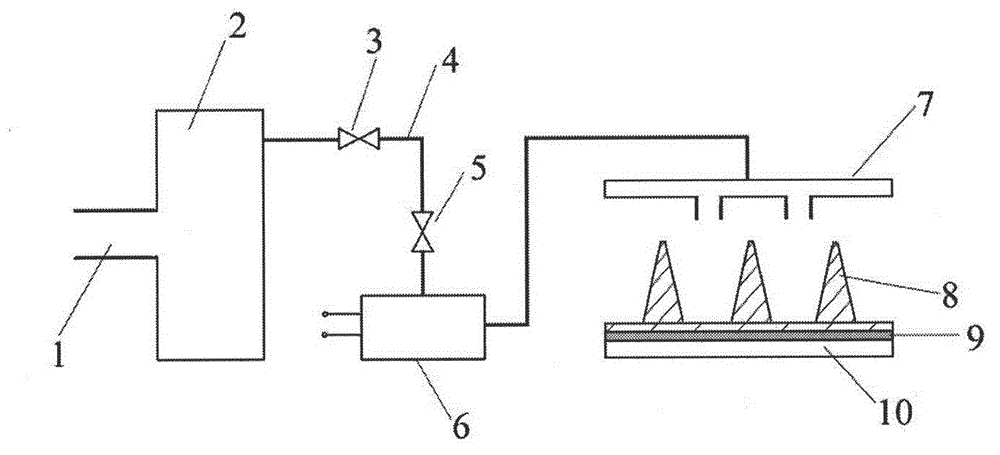
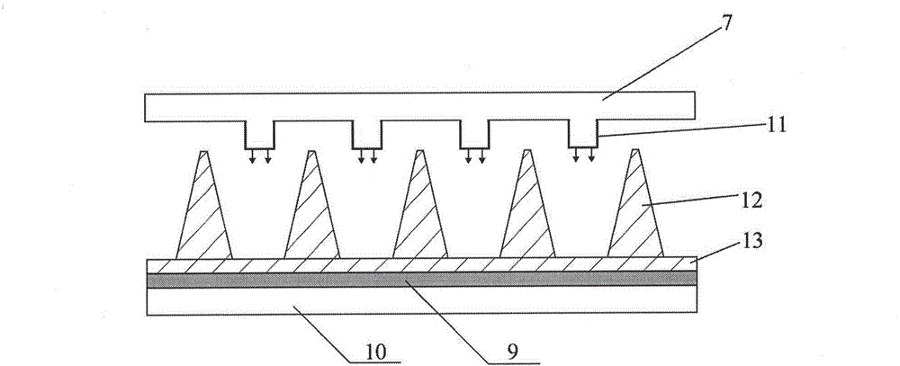
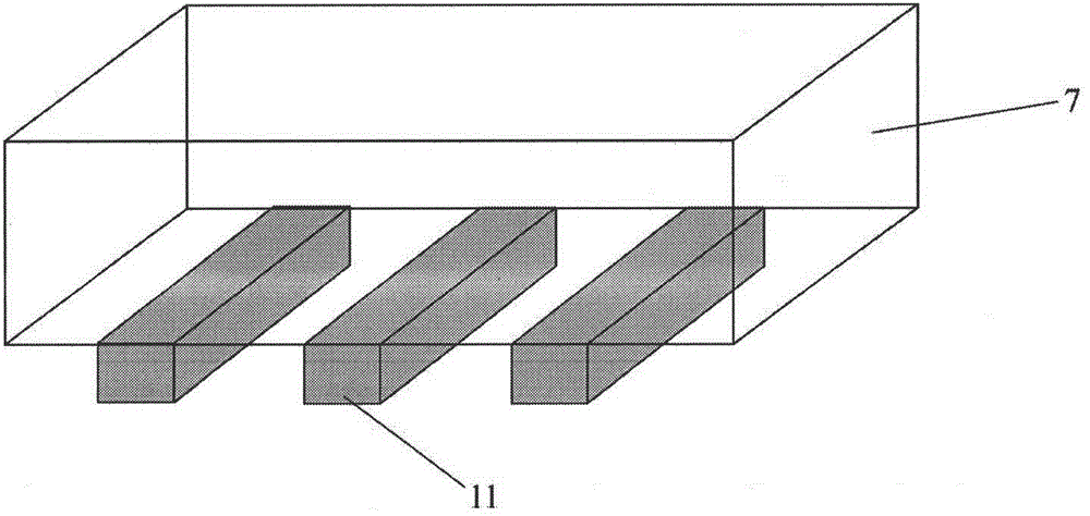
[0014] Such as figure 1 As shown, the present invention includes two parts: a pulsating flow generating device and a jet fin radiator. The gas enters the air compression cylinder 2 from the inlet 1, controls the flow of air in the pipeline 4 through the switch valve 3 and the pressure control valve 5, and enters the electronic signal to drive the steady-state air flow in the acoustic excitation device 6 to convert into a pulsating flow, and the pulsating flow enters The jet array 7 directly hits the surface of the fin 8 through the slit nozzle. The speed of the steady-state airflow entering the electronic signal-driven acoustic excitation device 6 is set by the pressure control valve 5. After the steady-state airflow enters the electronic signal-driven acoustic excitation device 6, it can be converted into an unsteady flow according ...


PUM


Abstract

The invention relates to a cooling device of an electron device, in particular to a pulse jet flow finned cooling device which is a high-efficiency cooling device with a pulse jet flow cooling technology and a finned radiator combined. The pulse jet flow finned cooling device mainly comprises a pulsating flow generating device, a jet flow matrix and the finned radiator. The pulse jet flow finned cooling device is characterized in that an electronic signal drives an acoustic excitation device to generate an unsteady pulsating flow which is jetted onto the finned radiator through the pulse jet flow matrix. Due to the fact that cooling media directly impact the finned surface, and a heat transfer process is strengthened through the unsteady pulsating flow, cooling efficiency is improved, energy consumption is reduced, the electronic device with high heat flux density can be effectively and fast cooled, and jet flow parameters can be set according to requirements to adapt working condition changes.

Description

technical field [0001] The invention relates to a cooling system of an electronic device, in particular to a high-efficiency cooling device combined with a jet cooling technology and a fin radiator. Background technique [0002] With the continuous upgrading of integration and miniaturization of electronic devices, their power and integration degree have been greatly improved, and the heat flux density of power devices has been continuously rising. Heat dissipation has become a major obstacle to the further development of the microelectronics industry. Only by adopting appropriate cooling technology and structural design for heat-consuming components of electronic equipment and the whole machine or system, and controlling their temperature rise, can electronic equipment or systems work normally and reliably. For the new generation of electronic equipment, the design constraints and manufacturing techniques of traditional coolers cannot meet the requirements. [0003] Under ...

Claims


Application Information

Patent Timeline
IPC IPC(8): H05K7/20
Inventor 徐鹏邱淑霞乔宪武
Owner CHINA JILIANG UNIV
Why Eureka
Try Eureka