Protection system for electrical power distribution system using directional current detection and logic within protective relays

A technology of power distribution system and relay, applied in the direction of protection reacting to overcurrent, emergency protection circuit device, emergency protection device with automatic disconnection, etc., to achieve the effect of reducing fuel consumption and reducing emissions

Inactive Publication Date: 2013-06-12
SIEMENS AG
View PDF7 Cites 5 Cited by
  • Summary
  • Abstract
  • Description
  • Claims
  • Application Information

AI Technical Summary

Problems solved by technology

The use of ship management systems such as automated systems as part of protection schemes has been evaluated for some projects but has been abandoned in part due to problems with response times
May not want to be associated with additional systems for electrical fault protection

Method used


Image

  • Protection system for electrical power distribution system using directional current detection and logic within protective relays
  • Protection system for electrical power distribution system using directional current detection and logic within protective relays
  • Protection system for electrical power distribution system using directional current detection and logic within protective relays

Examples


Embodiment Construction

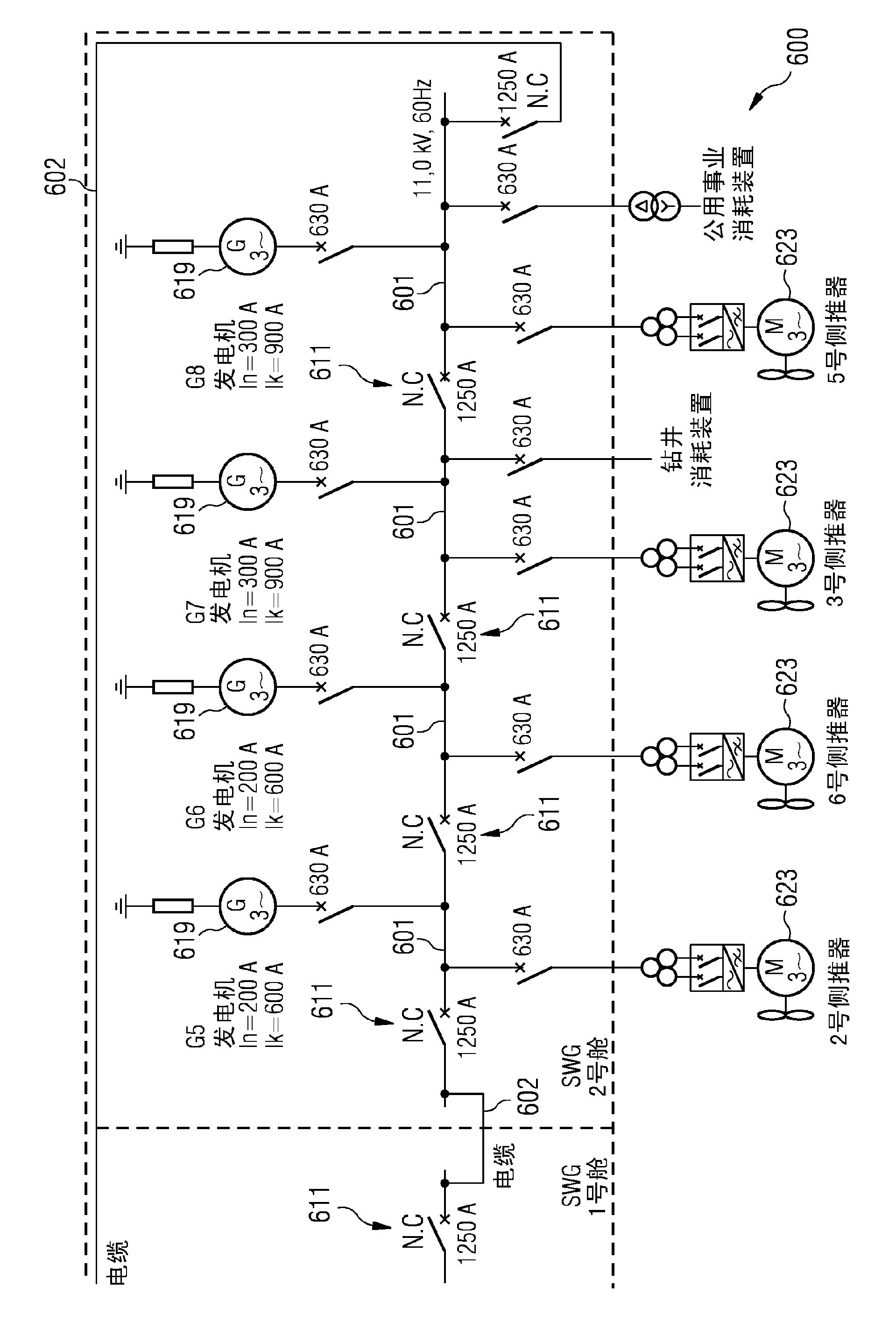
[0052] The illustrations in the figures are schematic. It should be noted that in different figures, similar or identical elements are provided with the same reference signs or with reference signs which differ from the corresponding reference signs only in the first position.

[0053] Fig. 1 schematically illustrates a power distribution system 100 according to an embodiment. The power distribution system 100 includes a plurality of buses, of which only a first bus 101 , a second bus 103 , a third bus 105 and a fourth bus 107 are illustrated. These buses are connected to each other by using a plurality of switches, of which only switches 109, 111, 113, 115 are shown. These buses are connected in series by using switches in an alternating fashion to form a ring 117 of alternating buses and switches.

[0054] The generator 119 is connected to the bus 103 via a switch 121 to supply electrical energy to the bus 103 . The electric energy supplied to the bus 103 is consumed by a...


PUM


Abstract

It is described a power distribution system for a dynamically positioned vessel. The power distribution system comprises: a plurality of busses (101,103,105,107) comprising a first bus (103) to which a load (123) is connectable; a plurality of switches (109,111,113,115) comprising a first switch (111) and a second switch (113), wherein the plurality of busses is connected via the plurality of switches in an interjacent manner to form a ring (117), the first bus is connected in between the first switch and the second switch. The power distribution system is configured to open the first switch and concurrently open the second switch, if a first current (149) flowing via the first switch in a direction towards the first bus is above a predetermined current threshold for longer than a predetermined time duration and a second current (143); flowing via the second switch in a direction towards the first bus is above the predetermined current threshold for longer than the predetermined time duration, thereby disconnecting the first bus from the ring while all other buses remain connected together. Further a method of power distribution and a vessel are provided.

Description

technical field [0001] The present invention relates to an electrical power distribution system, in particular to an electrical power distribution system for a dynamically positioned vessel (vessel), and to a method for power distribution, in particular to an electrical power distribution system used in Directional overcurrent fault protection with programmable logic available inside modern protective relays. In particular, the present invention relates to enhanced power distribution directional fault current protection using programmable logic within the protective relay, which is particularly suitable for such as those found on dynamically positioned ships The isolated power system (isolated power system), where high reliability is required. Also in particular, the invention relates to an electric power distribution system, in particular for a dynamically positionable vessel, wherein the electric power distribution system has a ring topology, enabling measures to be taken w...

Claims


Application Information

Patent Timeline
Patent Type & Authority Applications(China)
IPC IPC(8): H02H3/08B63B39/08
CPCB63H23/24B63H25/42H02H3/05H02H3/081H02H7/261B63B39/08H02H3/08H02H7/22
Inventor T.赫文
Owner SIEMENS AG
Why Eureka
Try Eureka