Supercharge Your Innovation With Domain-Expert AI Agents!

Ceramic filtration plate cleaning method

A ceramic filter plate and post-filtration technology, which is applied in the direction of filtration separation, separation method, filter regeneration, etc., can solve the problems of reduced filtration efficiency, ceramic filter plate scrapping, inconvenience, etc., and achieve the effect of improving cleaning efficiency

Active Publication Date: 2013-06-19
曹辉
View PDF5 Cites 2 Cited by
  • Summary
  • Abstract
  • Description
  • Claims
  • Application Information

AI Technical Summary

Problems solved by technology

[0002] In the prior art, most of the cleaning of the ceramic filter plate uses high-pressure water flow to wash the surface of the filter plate. Although this method can remove the impurities attached to the surface of the ceramic filter plate, the impurities that enter the interior of the ceramic filter plate during the water filtration process Even because the flushing water pressure is too high, the impurities on the surface of the filter plate will be squeezed into the interior of the ceramic filter plate, which will not only reduce the quality of the filtered water in the later stage, but may also lead to the deterioration of the filter layer of the ceramic filter plate. The clogging of the voids will reduce the filtration efficiency, and the long-term working state will also lead to the scrapping of the ceramic filter plate; at the same time, the ceramic filter plate cleaned according to the above method has a high water content, and it needs to be dried by other drying equipment or placed for a long time It is very inconvenient to store in later or

Method used


Image

  • Ceramic filtration plate cleaning method
  • Ceramic filtration plate cleaning method
  • Ceramic filtration plate cleaning method

Examples


Embodiment 1

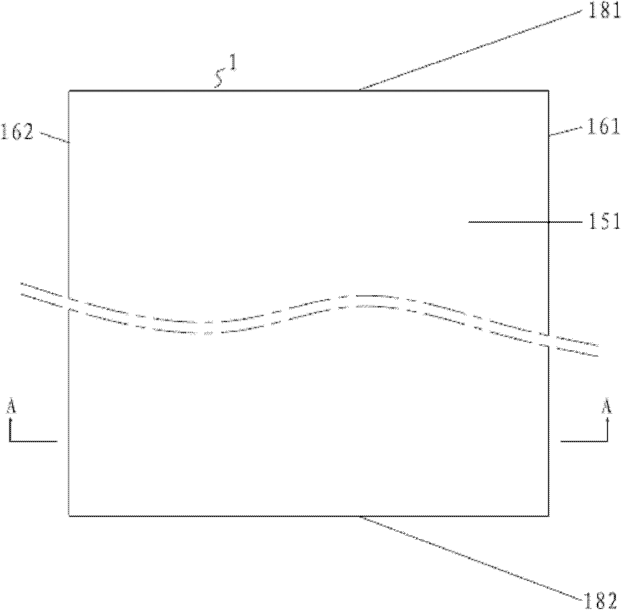
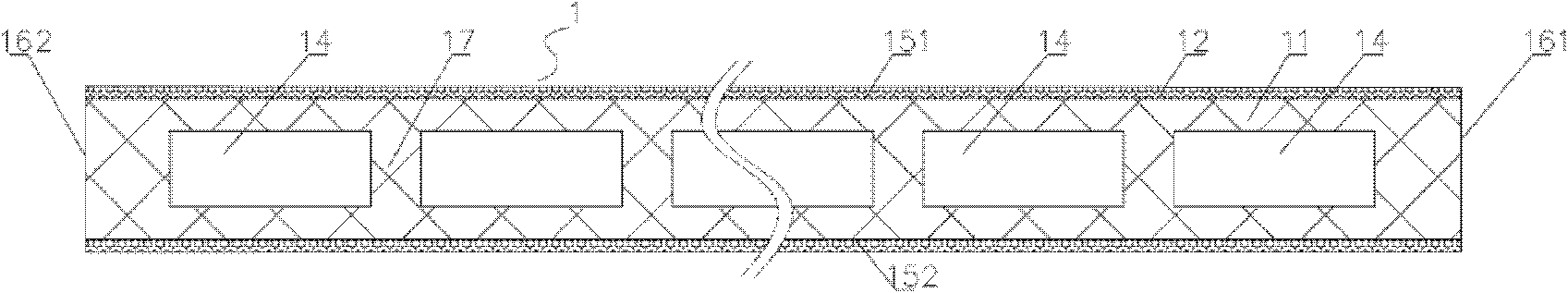
[0025] see figure 1 and figure 2 , the ceramic filter plate 1 described in this embodiment includes a ceramic substrate 11, and the ceramic substrate 11 includes two end surfaces 181 and 182, two side surfaces 161 and 162, and two mutually parallel bottom surfaces 151 and 152, and the ceramic The base plate 11 is provided with a cavity that runs through the two end faces 181 and 182 respectively. The cavity is used to store the filtered water. The cross-sectional shape of the cavity is a rectangle. The intersection lines of the plane and the bottom surface 151 (or 151) of the ceramic substrate are parallel to each other, and the ceramic substrate 11 is spray-coated with a nano-ceramic film 12 on the bottom surface, and the nano-ceramic film 12 is provided with irregular pores. The parallel bottom surfaces 151 and 152 can be curved surfaces, such as in a wavy shape. In this case, the overall shape of the ceramic substrate 11 is also wavy. The parallel bottom surfaces 151 and ...

Embodiment 2

[0037] The difference between this embodiment and Embodiment 1 is that the ceramic filter plate in this embodiment is a ceramic filter plate commonly used on an existing vacuum filter.

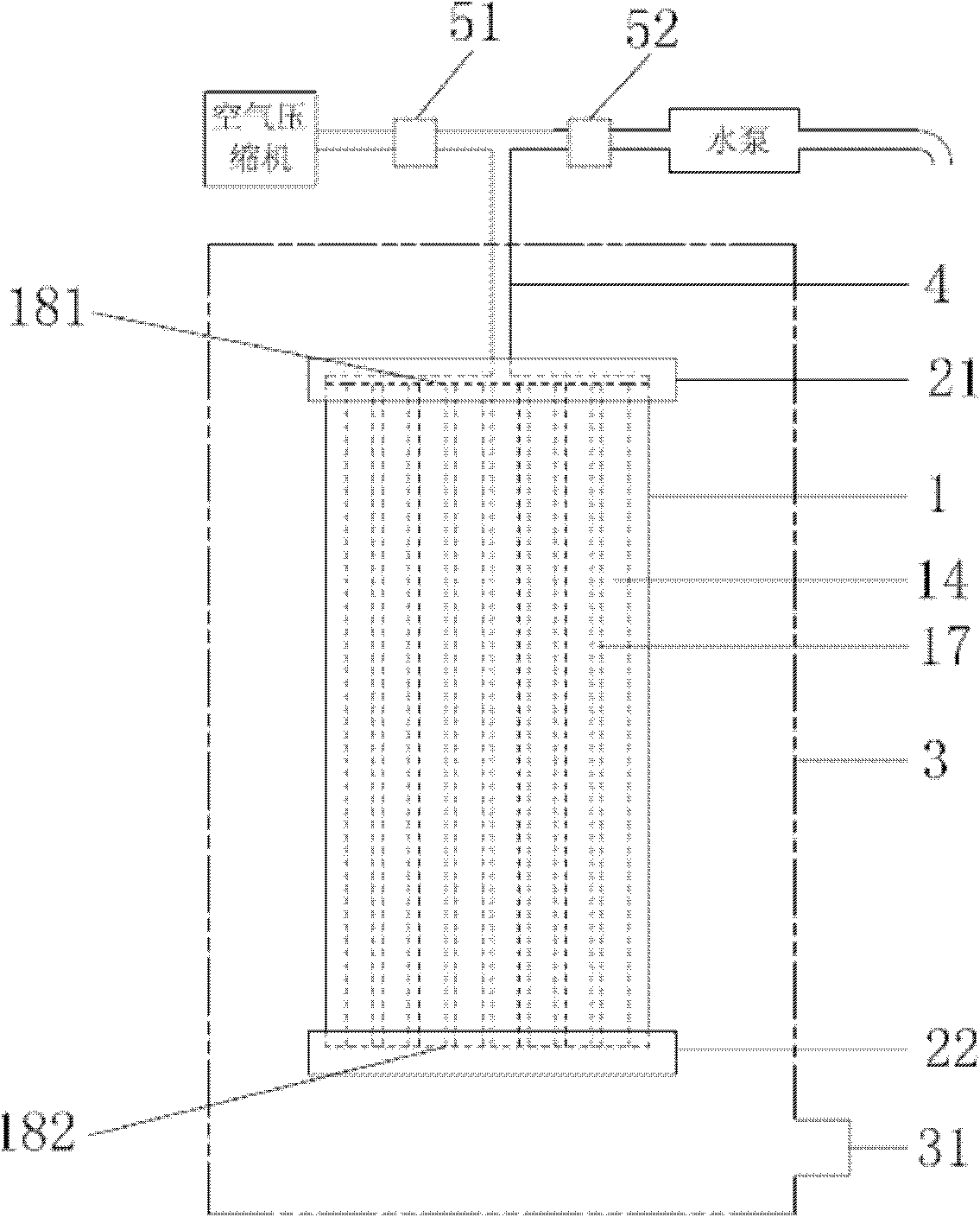
[0038] see Figure 4 , the ceramic filter plate 1' in this embodiment has a fan-shaped structure, and it has an installation hole 61 near the edge. The ceramic filter plate 1' includes a base body 63, and the outer surface of the base body 63 is coated with a filter coating. The base body 63 is provided with a cavity for storing filtered water, and the cavity forms water storage channels 62 distributed in the base body regularly or irregularly. There is also a drainage hole 64 on the top, one end of the drainage hole 64 is connected to the water collection channel 65, and the other end is connected to the air pipe 4 through the sealing joint 21', and the air pipe 4 is connected to the air compressor through the switch valve 51.

[0039] Based on the above structure, the ceramic filter plate c...


PUM


Abstract

The present invention relates to a ceramic filtration plate cleaning method. According to a ceramic filtration plate with a built-in cavity, the cavity is provided for storing a filtered water body, and is communicated with the outer part of the ceramic filtration plate through water discharge holes. According to the cleaning method, compressed air is introduced to the cavity inside the ceramic filtration plate so as to achieve ceramic filtration plate cleaning, such that impurities deposited inside the ceramic filtration plate are blown out of pores from inside to outside so as to improve filtration water quality and prolong a service life of the ceramic filtration plate, and gas and moisture escaping from the ceramic filtration plate during a cleaning process form a layer of a gasification water mist film on the surface so as to remove pollutants attached on the surface of the ceramic filtration plate in an extremely short time and substantially improve cleaning efficiency of the filtration plate. In addition, the ceramic filtration plate cleaned by using the method has low water content, and can be subjected to direct warehousing, such that cost for the intermediate steps from cleaning to warehousing in the conventional method can be saved, and the method is a cleaning method with characteristics of convenient operation, rapidness and efficiency.

Description

technical field [0001] The invention relates to a cleaning method for water treatment accessories, more particularly, to a cleaning method for a ceramic filter plate. Background technique [0002] In the prior art, most of the cleaning of the ceramic filter plate uses high-pressure water flow to wash the surface of the filter plate. Although this method can remove the impurities attached to the surface of the ceramic filter plate, the impurities that enter the interior of the ceramic filter plate during the water filtration process Even because the flushing water pressure is too high, the impurities on the surface of the filter plate will be squeezed into the interior of the ceramic filter plate, which will not only reduce the quality of the filtered water in the later stage, but may also lead to the deterioration of the filter layer of the ceramic filter plate. The clogging of the voids will reduce the filtration efficiency, and the long-term working state will also lead to...

Claims


Application Information

Patent Timeline
Patent Type & Authority Applications(China)
IPC IPC(8): B01D41/04
Inventor 曹辉
Owner 曹辉
Features
  • R&D
  • Intellectual Property
  • Life Sciences
  • Materials
  • Tech Scout
  • Unparalleled Data Quality
  • Higher Quality Content
  • 60% Fewer Hallucinations
Learn More