Silicon microgyroscope performance improving method and device based on force balance closed-loop control

A technology of silicon micro-mechanical and closed-loop control, which is applied in the direction of measurement devices, gyro effect for speed measurement, gyroscope/steering sensing equipment, etc. Coupling errors and other issues can be improved to improve detection accuracy and measurement and control performance, improve the signal-to-noise ratio of sensitive output, and eliminate quadrature errors

Active Publication Date: 2013-06-19
NAT UNIV OF DEFENSE TECH
View PDF3 Cites 31 Cited by
  • Summary
  • Abstract
  • Description
  • Claims
  • Application Information

AI Technical Summary

Problems solved by technology

However, due to machining accuracy and manufacturing errors, there are various coupling errors in the micro-gyroscope structure, resulting in the deviation of the elastic stiffness principal axis from the design principal axis, resulting in modal coupling errors
As a result, when the gyro has no angular velocity input, it still applies a large vibration force signal to the sensitive end, which seriously affects the gain setting of the pre-op amplifier and greatly reduces the signal-to-noise ratio of the sensitive output.
At the same time, due to the limitation of the accuracy of the phase shifter, there is a phase difference, which cannot completely eliminate the quadrature error, which seriously affects the improvement of the measurement and control performance of the micro-machined gyroscope, and restricts the development of high-performance micro-machined gyroscopes.

Method used


Image

  • Silicon microgyroscope performance improving method and device based on force balance closed-loop control
  • Silicon microgyroscope performance improving method and device based on force balance closed-loop control
  • Silicon microgyroscope performance improving method and device based on force balance closed-loop control

Examples


Embodiment Construction

[0034] The implementation steps of the silicon micromachined gyroscope performance improvement method based on force balance closed-loop control in this embodiment are as follows:

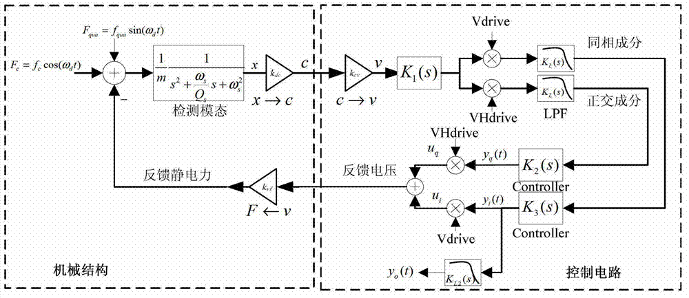
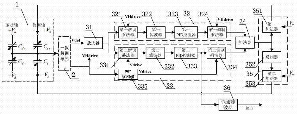
[0035] 1) Amplify the detection signal output by the primary demodulation unit of the silicon micromechanical gyroscope in sequence, perform secondary demodulation, filtering, and PID control according to the driving signal to obtain the amplitude of the quadrature coupling error signal, and convert the amplitude of the quadrature coupling error signal to Modulating to the drive signal to obtain a quadrature coupling error signal;

[0036] 2) The drive signal output by the primary demodulation unit of the silicon micromachined gyroscope is shifted by 90° to obtain the drive quadrature signal, and the detection signal output by the primary demodulator unit of the silicon micromachined gyroscope is amplified in sequence, and according to the drive quadrature signal Perform secondary demodulation, fil...


PUM


Abstract

The invention discloses a silicon microgyroscope performance improving method and device based on force balance closed-loop control. The method comprises the following steps that: a detecting signal is modulated to a driving signal after being subjected to demodulation, filtering and PID control by the driving signal, thus acquiring a cross coupling error signal; a driving orthogonal signal which obtained by carrying out 90-degree phase shift on the detecting signal by the driving signal is subjected to demodulation, filtering and PID control so as to obtain a Coriolis signal; the cross coupling error signal and the Coriolis signal are overlapped and are loaded to the detecting electrode of a silicon microgyroscope together with a bias direct current. The device comprises an amplifier, a 90-degree phase shifter, a cross coupling error signal acquiring unit, a Coriolis signal acquiring unit, an adding device and a voltage output unit. According to the invention, force applied to detecting a quality block is counteracted so as to keep a detecting element at an original place, therefore, the influences of large cross coupling error, characteristic parameter drifting, phase difference in synchronous demodulation and the like on the performance of the silicon microgyroscope can be effectively avoided.

Description

technical field [0001] The invention relates to the field of silicon micromechanical gyroscopes, in particular to a method and device for improving the performance of silicon micromechanical gyroscopes based on force balance closed-loop control. Background technique [0002] Silicon micromachined gyroscopes are generally composed of support beams and mass blocks, mostly in the form of electrostatic drive and capacitive detection. Silicon micromachined gyroscope includes two modes: drive mode and detection mode. The mass block undergoes simple harmonic vibration along the driving axis direction (x-axis) under the action of the driving electrostatic force, which is called the driving mode; when there is an angular velocity signal along the angular velocity input direction (z-axis), the force produced by the Coriolis effect The Coriolis force causes the proof mass to vibrate in the direction of the detection axis (y-axis), which is called the detection mode. The detection mod...

Claims


Application Information

Patent Timeline
Patent Type & Authority Applications(China)
IPC IPC(8): G01C19/5776
Inventor 肖定邦吴学忠胡小平陈志华苏剑彬侯占强刘学张旭
Owner NAT UNIV OF DEFENSE TECH
Why Eureka
Try Eureka