Mixing optics current transformer and method for achieving self-correcting measurement thereof

A current transformer and hybrid technology, applied in the field of sensors, can solve the problems of poor linearity, temperature drift of measurement accuracy, etc., and achieve the effect of eliminating influence, overcoming temperature drift, and eliminating changes in permeability and temperature.

Active Publication Date: 2013-06-19
HARBIN INST OF TECH
View PDF7 Cites 12 Cited by
  • Summary
  • Abstract
  • Description
  • Claims
  • Application Information

AI Technical Summary

Problems solved by technology

[0005] In order to solve the problem of linearity difference and temperature drift of measurement accuracy existing in the existing hybrid optical current transformer, the present invention proposes a hybrid optical current transformer and its method for realizing self-calibration measurement

Method used


Image

  • Mixing optics current transformer and method for achieving self-correcting measurement thereof
  • Mixing optics current transformer and method for achieving self-correcting measurement thereof
  • Mixing optics current transformer and method for achieving self-correcting measurement thereof

Examples


specific Embodiment approach 1

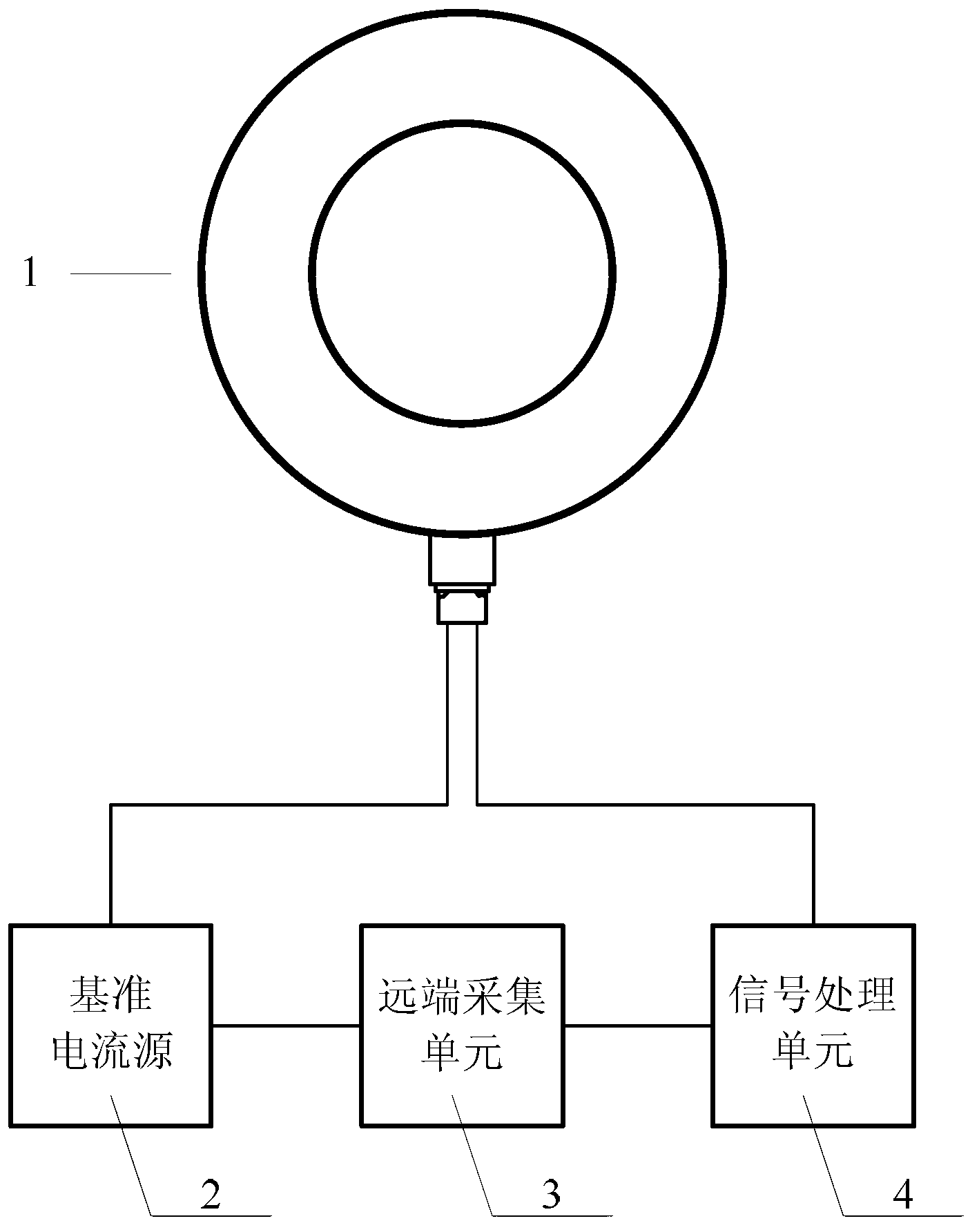
[0026] Specific implementation mode one: see figure 1 , figure 2 and image 3 Describe this embodiment mode, a kind of hybrid optical current transformer described in this embodiment mode, it comprises hybrid sensor head 1, reference current source 2, remote acquisition unit 3 and signal processing unit 4,

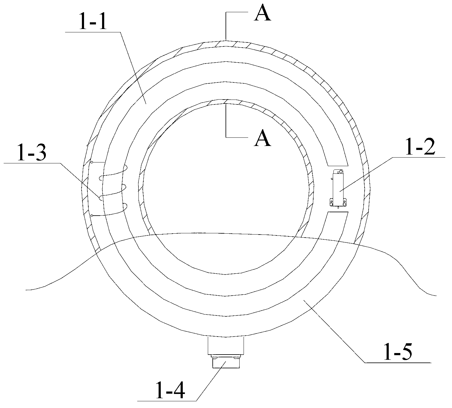
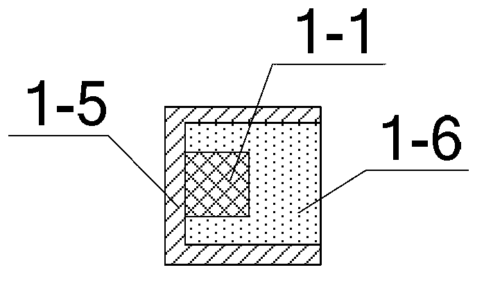
[0027] The hybrid sensor head 1 includes a magnetic collecting ring 1-1, an optical sensing unit 1-2, a self-calibration module 1-3, an aviation plug 1-4, a base 1-5 and an epoxy glue 1-6,

[0028] The base 1-5 is a circular base, and the base 1-5 is a U-shaped groove structure. The magnetic collecting ring 1-1, the optical sensing unit 1-2 and the self-calibration module 1-3 are installed on the base 1-5. 5, the magnetic collecting ring 1-1 is provided with an air gap, the optical sensing unit 1-2 is provided in the air gap, and the self-calibration module 1-3 is composed of a hollow solenoid. The hollow solenoid is sleeved on the magnetic collecting ring 1-1, and is ...

specific Embodiment approach 2

[0032] Embodiment 2: This embodiment is a further limitation of the hybrid optical current transformer described in Embodiment 1. The optical signal output and input ends of the optical sensing unit 1-2 are optically connected to the signal processing unit 4 through an optical fiber. The signal output and input ends are connected, and the optical fiber is a multimode optical fiber.

specific Embodiment approach 3

[0033] Specific implementation mode three: see Figure 4This embodiment is described. This embodiment is a further limitation of the hybrid optical current transformer described in Embodiment 1. The optical sensing unit 1-2 includes a collimator 1-2-1, a polarizer Device 1-2-2, magneto-optic crystal 1-2-3, beam splitting prism 1-2-4, first coupler 1-2-5 and second coupler 1-2-6, optical sensing unit 1- The light input from the optical signal input end of 2 is incident to the collimator 1-2-1, and output to the polarizer 1-2-2 through the collimator 1-2-1, and then passed through the polarizer 1-2-2 After being transmitted, it is incident on the magneto-optic crystal 1-2-3, and after being transmitted by the magneto-optic crystal 1-2-3, it is incident on the beam splitting prism 1-2-4, and the transmitted light after being transmitted by the beam splitting prism 1-2-4 is incident on the first A coupler 1-2-5, the reflected light reflected by the beam-splitting surface of the b...


PUM


Abstract

The invention discloses a mixing optics current transformer and a method for achieving self-correcting measurement thereof, belongs to the technical field of sensors, and particularly relates to an optics current transformer. The mixing optics current transformer and the method for achieving self-correcting measurement thereof solve the problems existing in an existing mixing optics current transformer of poor linearity and measurement accuracy temperature drifts. According to the mixing optics current transformer, an optics sensing unit is connected with a signal processing unit, a reference current source is connected with a far-end collecting unit and a self-correcting module, the far-end collecting unit is connected with the signal processing unit, and the signal processing unit is connected with the far-end collecting unit. The method for achieving the self-correcting measurement includes that, light sent by a light emitting diode (LED) light source is transmitted to the optics sensing unit; the optics sensing unit induces an electric current to be detected and transmits obtained linear polarized light back to a photoelectric detector; two paths of identical signals are transmitted to an industrial frequency filter and a high pass filter; digital signals are obtained by processing the identical signals; and a digital signal processor (DSP) uses a self-correcting algorithm to process the digital signals according to reference current signals. The mixing optics current transformer and the method for achieving self-correcting measurement thereof are suitable for an electric power system.

Description

technical field [0001] The invention belongs to the technical field of sensors, and in particular relates to an optical current transformer. Background technique [0002] Current transformers are indispensable power equipment in power systems. The hybrid optical current transformer adopts the magnetism collecting ring and the optical current sensor to measure. It combines the advantages of the electromagnetic current transformer and the optical current transformer. The use of the magnetic ring can improve the performance of the hybrid optical current transformer. Anti-interference ability of external magnetic field, its good magnetic gathering ability can also greatly enhance the magnetic field at the optical current sensor, thereby improving the sensitivity of the hybrid optical current transformer; the optical current sensor has AC and DC measurement capabilities, and can measure the current to be measured Holographic measurements. However, the magnetic collecting ring i...

Claims


Application Information

Patent Timeline
Patent Type & Authority Applications(China)
IPC IPC(8): G01R15/24G01R19/25
Inventor 郭志忠李深旺张国庆于文斌王贵忠申岩路忠峰
Owner HARBIN INST OF TECH
Why Eureka
Try Eureka