
Fluorescent lampshade type light-emitting diode (LED) white light module

A fluorescent lamp and module technology, applied in the field of fluorescent lampshade type LED white light modules, can solve the problems of poor effect, high cost, complicated design and production, etc.

Inactive Publication Date: 2013-06-19
SHANGHAI JIATANG ELECTRONICS DEV
View PDF6 Cites 1 Cited by
  • Summary
  • Abstract
  • Description
  • Claims
  • Application Information

AI Technical Summary

Problems solved by technology

[0005] In order to produce a large-angle light-emitting module, someone designed an optical reflection lens made of transparent PC and other materials, and placed the optical lens on the LED light-emitting tube to increase the light-emitting angle of the module. However, due to the LED light-emitting tube, special It is a high-power LED light-emitting tube, which may be composed of multiple chips. However, the design and manufacture of optical lenses is complicated, the cost is high, and the effect is not good.
In addition, the lens itself has a large light transmission loss for LED white light, resulting in low luminous efficiency of the module
Apparently, the defect of using the lens technology is very obvious, and it will also increase the manufacturing cost of the module

Method used


Image

  • Fluorescent lampshade type light-emitting diode (LED) white light module
  • Fluorescent lampshade type light-emitting diode (LED) white light module
  • Fluorescent lampshade type light-emitting diode (LED) white light module

Examples


Embodiment 1

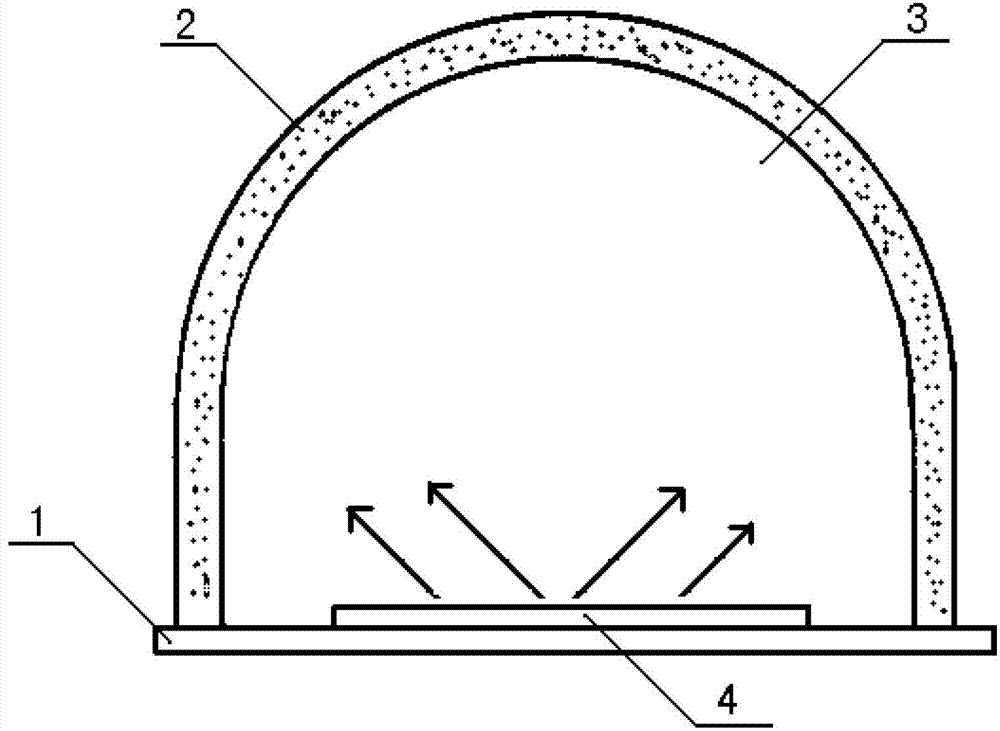
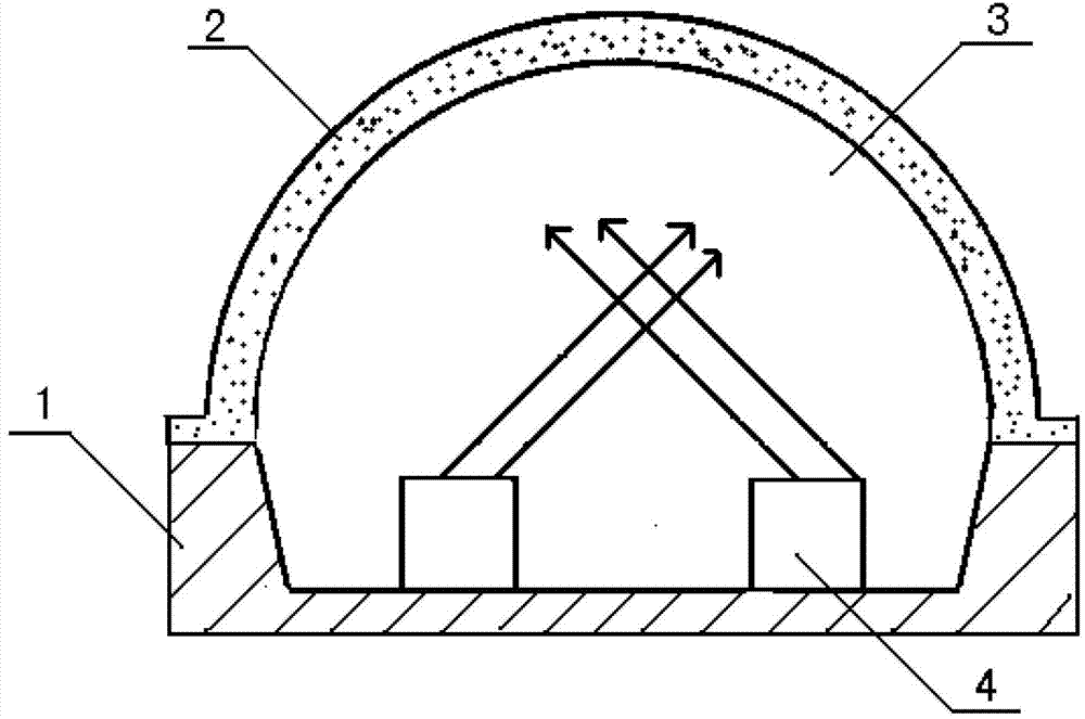
[0049] 1. Use 100 parts by weight of liquid transparent epoxy resin or silica gel as the base material, then add 0.3-10 parts by weight of yellow fluorescent powder for LEDs in proportion, mix thoroughly, and then use ordinary casting method or pressurized gelation molding The technology injects the liquid mixture into the lampshade mold, and depending on the solidification characteristics of the base material, a qualified solid LED lampshade containing uniformly distributed phosphors can be obtained after a few minutes to a few hours.

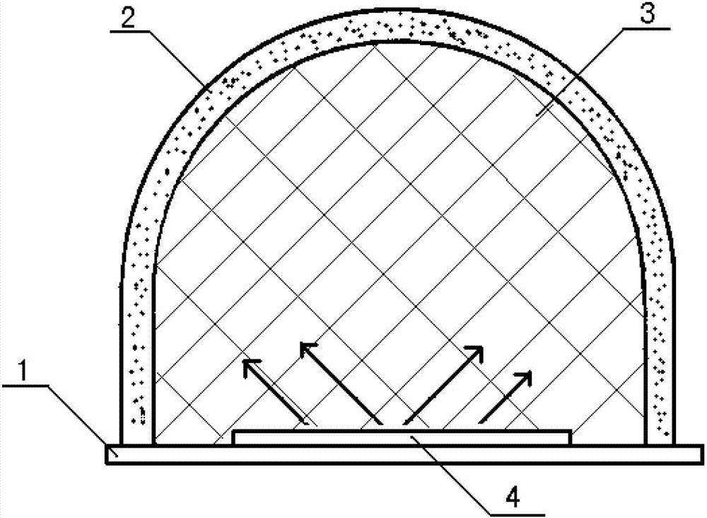
[0050] 2. Then pour a transparent layer (silica gel or epoxy) inside the solid LED lampshade containing phosphor, and after the transparent layer is cured, the lampshade of the large-angle module is obtained.

[0051] 3. Put the lampshade on the blue LED light-emitting tube (or light-emitting assembly) to fix it, and you can get a large-angle LED module.

Embodiment 2

[0053] 1. It is also possible to use transparent materials such as plastics and PCs mixed with phosphor powder at a ratio of less than 15%, and obtain solid LED masks containing phosphor powder by injection molding and other methods.

[0054] 2. Then pour a transparent layer (silica gel or epoxy) inside the solid LED lampshade containing phosphor, and after the transparent layer is cured, the lampshade of the large-angle module is obtained.

[0055] 3. Put the lampshade on the blue LED light-emitting tube (or light-emitting assembly) and fix it to get a large-angle LED module

[0056] For the fluorescent lampshade type LED white light module proposed by the above technical solution, if liquid state epoxy resin and silica gel are used as the base material of the lampshade, and a certain amount of phosphor powder is added to the base material to make the lampshade, the molding is not only simple. Moreover, since the base material is liquid, the powdery fluorescent powder can be qu...


PUM


Abstract

The invention relates to a fluorescent lampshade type light-emitting diode (LED) white light module. The fluorescent lampshade type LED white light module is characterized in that a fluorescent lampshade mixed with fluorescent powder and provided with an arc-shaped top face is covered on a blue luminous body substrate plate composed of one or a plurality of blue luminous tubes, silica gel or epoxy resin is filled between a luminous body and the fluorescent lampshade to form a transparent layer, blue light emitted by the blue luminous body reaches the fluorescent lampshade through the transparent layer, and white light with a lighting angle from 200 degrees to 300 degrees can be stimulated after the blue light is combined with the fluorescent powder in the fluorescent lampshade.

Description

technical field [0001] The invention relates to LED advertising lighting module technology, in particular to a fluorescent lampshade type LED white light module capable of emitting light at a large angle. Background technique [0002] With the widespread use of LED lighting module technology in the field of advertising lighting, LED module lighting technology has developed rapidly. The main ways for current LED modules to produce white light are as follows: [0003] Use a blue LED chip, covered with a mixed layer of yellow phosphor and transparent colloid, to achieve white light emission. [0004] In the above-mentioned LED white light module technology widely used at present, the light-emitting tubes used to emit white light are placed flat on the substrate covered with circuits. Due to the limitation of the light-emitting angles of the substrate and light-emitting tubes, the light-emitting angles of the modules are generally less than 180 degree. [0005] In order to pr...

Claims


Application Information

Patent Timeline
Patent Type & Authority Applications(China)
IPC IPC(8): H01L33/48H01L33/56H01L33/50
Inventor 王小平徐强
Owner SHANGHAI JIATANG ELECTRONICS DEV
Learn More